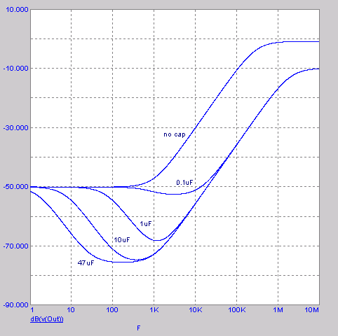
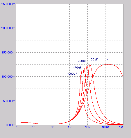
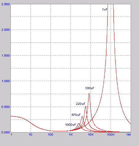
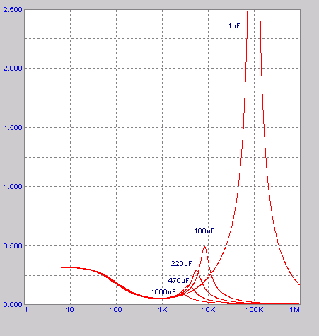
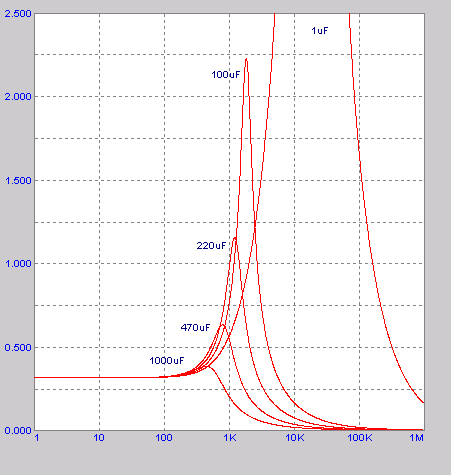
This is the
MicroCap
simulated power supply rejection of LM338 in the given circuit. It is
obviously very dependent on the value of the cap used as bypass for the
adjustment pin. It is commonly understood that 10uF is about right in this
place. (In these graphs parasitic properties of the capacitors are not modeled,
ideal capacitors are assumed.)
|
Next three graphs show the output impedance (in Ohms, of course) of LM338 driven by the zero output impedance (ideal) source. Curves show output impedance in the cases of five different output capacitors (C3/C4).
First graph shows the output impedance if 10uF bypass cap at LM338's adj pin is used. |
The way it
looks if 1uF cap is used here.
|
All else being equal, but no cap at all at the adj
pin. Note that Y axis is here 10 times taller.
|
Next three graphs correspond to the previous
three, but regulator is here driven by the source with 100 Ohms output
impedance. This impedance is assumed as purely resistive, so these curves
will look more complex in the real implementation.
10uF at the adj pin... |
...1uF...
|
...adj pin not
bypassed.
|
Please note - these Pedja Rogic archived pages are hosted as a service to the DIY community. Pedja no longer provides support or any help for these projects.