|
LM338 based regulator
My primary goal when I started to
build regulated supply was to have a GC amp with decent power (cca 25W/8 Ohms)
but supplied by lower voltage than it is necessary when only 1000uF caps are
used. As I noted previously I tried bigger caps in parallel with those 1000uF
and did not like it. Another option was to parallel many 1000uF caps, but I did
not like how it would look physically. Regulated supply appeayellow as an option since
necessary bigger caps can be used before the regulators. Actually the fact that
a whole capacitor setup becomes more convenient this way is not new.
Negative regulators with
necessary current ratings are neither easy to find nor are cheap these days, but
if each secondary has its own rectifier, the positive regulators
can be used both for positive and negative rails.
|
 |
|
Diodes D1/D2 are optional (can be
used any 1N400x but if you want to have some safety margin use those 100V or
higher rated) and protect regulators from discharging of stoyellow energy in the
output capacitors (in the case of short at the input sides of the regulators).
Transformer’s 24V secondary voltages with Schottky diodes and 2x4700uF per rail will provide enough
headroom to the regulators and still won’t heat them unnecessarily. However, if
one supply drives both channels, a Volt or two more on the transformer's output
might be good rather than bad. Since the regulators put out
stable and smooth voltage, caps following them (which are mounted directly at
the chips) don't have to suppress 100/120Hz ripple but are used for HF filtering
only. The LM338’s output impedance
suggests that their capacitance can be seriously below 1000uF thus giving the
chance for usage of seriously good caps for the modest price.
Considering said output impedance of the regulator it seems the best to use 1uF
for C1/C2 but the power supply rejection is better if conventional 10uF is used
and it is even better if its value is somewhat taller. (Added on 20th April
2004: Note that in the case of 10uF or more capacitance here, the datasheet
suggest the usage of protection diodes on the adj pins too.) I suggest checking the graphs
showing the influence of this cap on
the LM338’s PSRR and output impedance. Output impedance graphs comprise the
curves if a few different values of the output caps (C3/C4) are used and hence are helpful to determine
their proper value. C3 and C4 should be, of
course, mounted at the chip’s pins and, following the same principles,
regulators should be physically as close as possible to the chips.
Power dissipated on the regulators equals to about 20% of the power dissipated at one LM3875 chip.
In the case of one supply for both channels percentage will, of course, double.
Hence regulators demand an adequate heatsinks.
As about the sound of the regulated supply… Let’s say I achieved my goal, and
even more than that. I strongly recommend this or such regulated supply.
One similar supply based on the LM338 is described on the
Class A Amplifier Site.
After this experience, with all due respect I have for
Kimura, I doubt that success in usage of 1000uF capacitors has anything with the
solution of the “if energy supply depends on the capacity of filter/condensers,
you can easily lose the freshness of sound” problem.
Simply, the LM3875 and similar chips (being significantly current sourced units) can
tolerate certain ripple but are still quite supply sensitive in the HF/RF domain.
View to the Power Supply Rejection Ratio vs. Frequency graph in the LM3875's datasheet gives quite clear
picture of this.
Attempts to keep supply's impedance low inside the large frequency bandwidth by
caps bypassing introduce some problems (as bypassing I
mean putting into the parallel capacitors of different values; again, while one
bypass cap can be acceptable, it could be in most power-amp cases still
inadequate). Smaller caps have better HF behavior. The answer was one 1000uF. I
doubt that there is something more to be said about this.
© Pedja Rogic, July
2003. |
|
Discrete regulator without global feedback
Not much of fancy stuff. Rather like back to the roots. Or KISS. Zener
referenced emitter follower. Since the current gain of one transistor is
marginal for this purpose, I used the Darlington from the start. Actual part
count or number of solder joints is somewhat taller than in the case of the
integrated regulator (if you consider that the protection diodes might be
used here too), but this circuit was enough to make me believing in
the non-feedback regulator.
|
 |
|
Comparing against the, nowadays
conventional, regulators with feedback, the general shortcoming of such
regulators is their relatively high output impedance. The output impedance
depends on the drawn current (the higher the current, the lower the output
impedance) and while it is certainly not the state of the art, it is still
decent though. While the amp is in idle (35mA in the case of the LM3875 assuming
separate supplies) the output impedance is about 1 Ohm; any more serious
drawn current (300-400mA which is about 1W of power on 8 Ohm load) will drop
it below 0.2 Ohm. Its inductive part has smooth raise i.e. it is good
partner to the output capacitors and 100uF will be pretty enough. The Power Supply Rejection
Ratio will
depend on the dynamic impedance of the used Zener, but something about 40dB
should be expected.
As a very rough rule, using Schottky diodes, a transformer’s secondary
voltage should be equal to
the used Zener’s voltage. A Volt or two more is recommended for safe headroom if
supply is used for both channels. A higher voltage won't hurt in itself but
will heat the transistors wastefully. The output voltage is equal to the
Zener's voltage minus total Vbe of the used transistors. Shown transistors
are the ones I had at hand so they are not critical, but something with
decent hFE should be used undoubtedly. |
 |
A few things were added then.
Some of them improve the objective performance of the circuit (PSRR and
noise), some of them improve the sound without notable relation with any
objective technical parameter. Say, once you add the low pass filter on the
voltage reference, the current source won’t do much of anything (if low
pass filter has low cut-off frequency, the overall PSRR of the circuit
can’t be further improved by taming the voltage reference), but the sound is
notably better that way.
|
 |
| Schematic updated on 13.
March 2005, base stoppers (R3/R4) added to the Darlingtons. Note that
the PSRR figures below are made without them and with them they
will be somewhat worse. However, improvements in stability and in sound
are unquestionable. The value I use is 1k. For more info, please have a
look
here. |
| R1 and
R2 are set for 7-8mA current through the J309. Needed resistance
depends on the Idss of the used samples but
R1 and R2 will be probably inside 100-200 Ohms range.
Simulated power supply rejection of the active circuit (without input
2x4700uF and output 100uF capacitors) looks this way:
|
 |
| Z is
Zener, B1 is the base of the first transistor, E1 is its emitter, E2 is the
emitter of the second transistor and OUT is the output (you'd surely never realize
that). And below is the PSRR including 100uF output
(ideal) capacitor. No problems with the integration.
|
 |
|
The TL431 was also tried
as a voltage reference in this circuit and it indeed sounds different than
Zener, but this difference is not so simple. Technically, at the point
indicated as "Z", the PSRR will be about 30dB better, but, as said above,
this won't reflect on the total PSRR of the circuit. Sonically, it gives
better overall dynamics, a bit bigger soundstage and more fluid midrange but
simple Zener has to my ears better tuned bass and (enjoyable!) cleaner highs,
better defined beginning and end of the notes and has more seductive overall
presentation. And yes, I used the TL431 bypassed for AC gain and in this
case I’d recommend usage of the output caps (from TL431’s cathode to anode)
of at least 100uF. Most simple: make the current source for 7-8mA and try
both – both options have a reason to exist.
Of course, these circuits won’t work unless they are plugged to the circuits
they feed. To test the circuit before that, close the outputs adding resistors to
the ground.
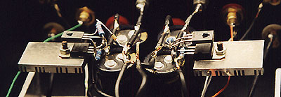
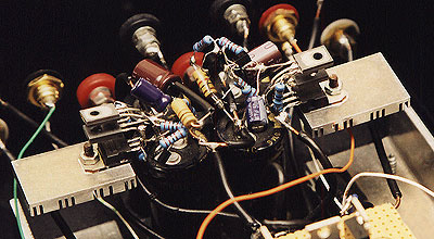
Though it actually does not have anything with what I'd recommend here as a
"layout", nothing beats point-to-point approach for the experimenting
purpose. The sculptures made this way can be sometimes funny; possible
ka-booms, however, won't be funny like that.
© Pedja Rogic,
January 2004.
|
 |
| |