Introduction.
Stripping down.
Power supply mods.
Preamp section
Power amp section
Replacing trim pots
What else?
Hung up on DIY hi-fi?
Then welcome to

Modifying the Arcam A60 amplifier.
![]()
![]()
Decibel Dungeon
Introduction.
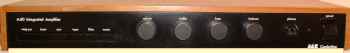
The A&R Cambridge (now Arcam) A60 integrated amplifier was produced between the mid 1970's and 1980's in the sort of quantities that very few other items of hi-fi have ever matched. Many thousands were sold to satisfied customers over that time and an amazing number are still in use today, some quarter of a century after the first A60 was produced.
IMPORTANT REMINDER - don't attempt any work on the mains parts of this amplifier if you are not competent to do so.
SECOND REMINDER - have a pencil and note pad handy and make a note of wiring connections and where bits go while you are dismantling. Also have a suitable container to put all the small parts in.
Stripping down.
It can be quite a long procedure to strip down the A60 in order to make modifications. However, there are no real technical difficulties involved.
- Remove the four control knobs by loosening the tiny screws which grip the shafts.
- Remove the screws which secure the wooden sleeve and remove it.
- Remove the connector which connects the transformer to the PCB.
- If the LED is connected to the PCB via wires and a connector, disconnect it.
- Disconnect the loudspeaker terminals (this varies depending on the model you are working on)
- Remove the four screws holding the front plate and remove it.
- Remove the four screws which secure the output transistors to the heat sink.
- Remove the screws which hold the PCB to the chassis.
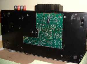 If you are going to follow the 'golden rule' of doing one modification at a time, you will, by this stage, be thinking that it will involve a lot of work, dismantling and reassembling the A60 so many times. I overcame this problem by cutting an aperture in the base plate of the casing so that I had access to most parts of the PCB just by removing the cover plate over the aperture.
Modifying the power supply.
- Replace the 120VA transformer with a 300VA equivalent (25-0-25 secondary windings). This will not fit in the slim case of the A60 so you will need to house it in a separate casing, either purchased or fabricated. Carefully desolder the wires on the original transformer from the plug which fits onto the PCB. Solder three extension wires onto the plug, twist them together and put some heat shrink tubing over them. The wires should be long enough to reach the new transformer but don't make them too long. An alternative is to use a shielded cable with three conductors if you are worried about picking up RF signals on this umbilical. I use a simple three-way terminal block to join the umbilical to the secondary leads of the new transformer.
- I prefer to use a combined 5 amp circuit breaker/switch instead of the on/off switch and mains fuse. The new 'switch' is mounted in the transformer case. See diagram 1.
- Make up a device from a tranzorb ( Farnell part no. 608-129) and a voltage dependent resistor (VDR Farnell part no. 319-065). It can be mounted in the terminal block as shown in diagram 1. Note that one leg of each component is soldered together and the 'loose' legs inserted in the terminal block so that this device is across the live and neutral mains supply.
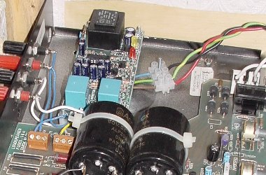
- Replace the smoothing capacitors C209 and C10. They will almost certainly be quite old and even standard replacements will make an improvement. I have used DNM slit-foil types which are based on the BHC Aerovox capacitors. The BHC Aerovox is also a good choice and considerably cheaper.
The capacitors are held on the with cable ties which you need to cut with a sharp knife or side-cutters. You will obviously need a couple of new ties to attached the new capacitors which are soldered to the stiff wires which protrude from the PCB.
Buy a couple of good polypropylene 4.7 microfarad capacitors to by pass the main smoothing caps. Bypass the 4.7's with 0.1 and 0.01 microfarad polypropylenes. Make sure that whichever type or brand you choose has a high enough voltage rating. Also check that there is enough space to fit the bypass capacitors. See diagram 2.
- Replace the four diodes (D204, D205, D207, D208) which form the rectifier bridge with something better such as the BYV79E-200 types.
- Remove the capacitor C211.
- Replace the other capacitors in the power supply section with the best you can afford, again making sure that the voltage ratings are high enough. These capacitors could also be bypassed with a 0.01 microfarad polypropylene if you wish. Note that the capacitor values and design of the power supply differ between models with serial numbers up to 13249 and those built afterwards.
- If you wish to modify the pre amp stage, you could also replace the LM317 and LM 337 voltage regulators with the AT types (if you can get them). Note that the earlier designs used regulators built from discrete components.
You will probably find that with the new capacitors installed, you are unable to replace the wooden sleeve. I overcame this problem by routing a recess into the sleeve.
The pre amp section.
Click HERE for circuit diagram.I have not actually done anything to the pre amp section of my A60's as they are used only as power amplifiers with a separate pre amp. However, I recommend the following modifications:
- Replace all electrolytic capacitors with better quality items.
- Replace the non-electrolytic capacitors with either polypropylene or polystyrene types.
- Things are not quite so clear with resistors. Arcam did bring out a revised model where they had replaced some, but not all, of the carbon film resistors with metal film types. In the power amp section I have used a mixture of metal film and carbon film and maybe that's a good compromise.
- The volume control and balance control should be replaced with at least ALPs items or better. I was advised that it is not possible to bypass the tone and balance control section very easily so I will not make that recommendation here.
- As regards the phono stage (if you use it), you could try replacing the op amps (earlier versions used transistors) with something better. The capacitors could be replaced with polypropylene types and the few resistors with Welwyn RC55 types as there are so few of them that cost is not an issue.
The power amp section.
Click HERE for circuit diagram.- As with the pre amp section, replace the capacitors with whatever you deem to be better.
- The capacitor C23 should be changed from a 470 picofarad to 680 or even 820 picofarads.
- The capacitors C32 and C33 could be replaced with up to 220 microfards depending on their physical size. I have used 220 microfarads but when soldered in place, I can no longer get to the screws which secure the output transistors to the heat sink. This isn't a problem as I can remove these capacitors by gaining access to them through the aperture in the base of the case.
- Some of the carbon film resistors could be replaced with metal film types. As a guide, the ones which Arcam chose to replace in their revised design are:
Value Part number 330R R1,17,18,24,101,117,118,124 2K7 R38,39,40,43,75,138,
140,143,1754K7 R15,26,115,126 6K8 R32,33,132,133 10K R22,23,27,28,29,34,45,
122,123,127,128,134,145
- Replacing resistors.
- The feedback resistors (R39, R46 and R47 are best replaced with the best items that you can afford. I used Welwyn RC55's which made a really noticeable improvement.
- I was also advised to replace the resistor R50 with a Welwyn RC55. As this affects the stability of the quiescent current, it is quite important to use something with a very low temperature coefficient (the RC55 is +/-15ppm). A further improvement would be to replace this resistor with an amplified diode which is explained below.
- The trim pot RV2 (used to set the quiescent current) is another suitable candidate for replacement with something better (or even just new)
- The feedback resistors (R39, R46 and R47 are best replaced with the best items that you can afford. I used Welwyn RC55's which made a really noticeable improvement.
- Changes to the circuit.
- I have removed all the fuses (FS201,FS202 and FS1) and replaced them with solid wire links. I have been using the amplifiers for over two years now with no problems. The A60 is a very stable amplifier and I feel that it is safe to remove these fuses IF you are very careful making sure that you don't cause short circuits on items like 'speaker cables.
NOTE that I also use 'speaker protection modules on the outputs of my amps. I use the Velleman modules built from kits..
- Run a wire from the leadout of R68 (see diagram) to the track between R66 and R67. Cut the track which goes from R68 to FS1.
- In order to provide a degree of isolation between the driver circuits and output transistors, I have used simple RC filters consisting of a 220 microfard capacitor (rated at 50 volts) and a 200 ohm resistor (0.6 watts). The filters are placed on each power rail as shown in the diagram (marked with a cross on each of the power rails). If you do this modification, be aware that you will need to put one of the filters on the underside of the PCB. It is not that difficult to do this modification once you have decided where to cut the tracks and insert the filters. I can confirm that the work is well worthwhile with bass particularly showing a marked improvement.
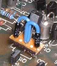
- The next modification has made the biggest improvement to the sound of the A60 and I am inbebted to Dr David White of White Noise for kindly providing the details.
It involves replacing resistor R50 with an amplified diode that greatly assists with thermal stablization that in turn improves the stability of the quiescent current.
The amplified diode consists of an NPN transistor and two resistors.
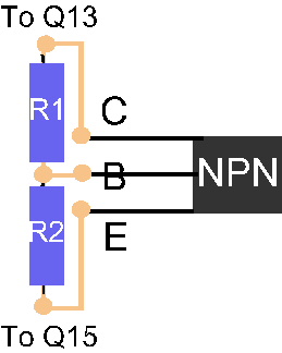 A trimpot in series with resistor R2 allows the amplified diode to be adjusted to set the quiescent current.
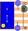
I built my amplified diodes using small pieces of stripboard, five strips by four holes (about 12mm by 10mm). With the resistors mounted vertically, their leadouts at either end of the stripboard are exactly spaced so as to drop into the holes left when R50 is removed.
 The value of the input resistor (R1) is 1K8, the trimpot (use a multiturn) is 500R and the end resistor is 470R. Any NPN transistor will do, I used a BC547.
There is space to fit one of these items in place of R50. For the other channel, file the stripboard as close to the trimpot as you can and use something to insulate the copper tracks from resistor R147.
The trimpot should be installed so that it is at maximum resistance when the screw adjuster is fully anti-clockwise and then set to maximum resitance. I connect the middle pin (wiper) to the output pin. Make sure that the transistor is inserted correctly and check all joints and resistances prior to inserting the diode.
I suggest that before you insert the amplified diode, you measure the quiescent current on each channel and adjust it if necessary so that it is set at 35ma, ie with a reading of 8mv across the output resistor R63. This is because the amplified diode will be used to adjust the quiescent current and RV2 will actually just set the standing current through the driver transistor.
Now install an amplified diode in the left channel. Switch on power and measure the voltage across R63. It should be no more than 1 or 2 millivolts. Very gradually, rotate the adjuster on the trim pot (the one on the diode) clockwise, and watch the voltage across R63. When it rises to 6mv, stop adjusting and watch the voltage. It will probably keep rising and if it goes much over 8mv, adjust the diode by turning the trim pot anti-clockwise by a small amount.
Be patient and keep checking (and adjusting) the quiescent current over a period of about 15 minutes. When you are happy that it has settled at around 35ma turn off the amplifier and repeat the process with the amplified diode for the other channel.
Run the amplifiers for a couple of days and then with the power OFF, measure the resistance across the trim pot and the end resistor. If you can get a fixed value VERY close to this resistance, you could replace the trim pot and end resistor with a single resistor but be warned, even a small change in resitance can affect the quiescent current quite a lot. The first time that I put in fixed resistors I found that I could only get a maximum of 25ma quiescent current. If you are planning on making more changes to the A60, it may be better to stick with the adjustable versions until you have finished.
Do remember, that with fixed value resistors, you will not be able to adjust the quiescent current if you need to later!
 Believe me, this modification makes a stunning improvement to the A60. Not surpprising as David White identified the R50 as the weak spot in the A60. I thoroughly recommend this mod to all A60 owners which is not difficult if you take the usual care in implementing it.
Just one word of caution based on my own experience. There's a need to make these diodes as small as possible and on one of my diodes, I managed to get a short across two adjacent tracks. Result - blown output transistors! So do double (and triple) check that your diodes are OK before you put them into the board and turn on the power.
- The A60 has a built in protection circuit which can be removed. The advice which I have been given regarding this modification is probably NOT to do it until you have finished doing all other work on the amp. Once you have and it is working without problems, then you can remove the circuit which comprises the following components:
- Diodes D1 and D2
- Transistors Q16 and Q17
- Resistors R54,R55,R56,R57,R58 and R59
- Capacitors C28 and C29
WARNING - If you do remove the protection circuit, you should use a loudspeaker protection module like the Velleman kit that is shown below.
- I have removed all the fuses (FS201,FS202 and FS1) and replaced them with solid wire links. I have been using the amplifiers for over two years now with no problems. The A60 is a very stable amplifier and I feel that it is safe to remove these fuses IF you are very careful making sure that you don't cause short circuits on items like 'speaker cables.
Replacing the trim pots
One component that should be replaced on most amplifiers is the cheap trim pot (trimmer) that is used to control the quiescent current to the output stage (more so if it is very old). If you want to know the reasons for this, see the article on TNT Audio by Dejan Veselinovic.![]() - I bought an adjusting tool at the same time as the trimmers. It cost under a couple of ponds but I didn't find it any easier than using a small insulated screwdriver. You may want to try one though.
- I bought an adjusting tool at the same time as the trimmers. It cost under a couple of ponds but I didn't find it any easier than using a small insulated screwdriver. You may want to try one though.
![]() - You will find it easier to do this rather than cutting off a piece of leadout wire and then trying to solder it onto the pin. It is easier to hold the resistor than a short length of leadout wire on its own!
- You will find it easier to do this rather than cutting off a piece of leadout wire and then trying to solder it onto the pin. It is easier to hold the resistor than a short length of leadout wire on its own!
Measure the distance from the two pins on the original trimmer to the single pin and then bend the leadout wire accordingly. If you have done this properly, you will find that the new trimmer will fit neatly into position on the PCB. BEFORE soldering the trimmer in, make sure that when you look at it from the front of the amplifier, the adjustment screw is on the right side.
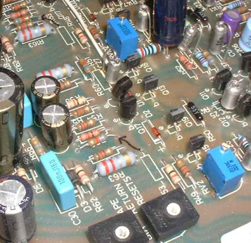
Here you can see the new cermet trimmers in place (the blue items with a screw on the top). The original single turn trimmers are the same as the tape return trimmers seen in the foreground of the above picture.
You can also clearly see the output resistors R63 and R163 which are used to measure the quiescent current.
For example, on the A60 the recommended voltage drop across R63 (which is a 0.22 ohm value) is 8mv so the current is .008v/.22 ohms = 36.36 ma.
What else?
I have not mentioned replacement of the transistors. The ZTX 653/ZTX753 are probably as good as you will get but the BC547's and TIP3055's can be improved upon although the replacements will have ecb pin outs instead of the ebc arrangement on the original items so some lead dressing will be necessary.I would like to take this opportunity to thank the following for their help and assistance with my A60 project:
- Arcam - for their help with circuit diagrams and advice. Any company who provides support for a product which they stopped producing over ten years previously should be considered very seriously when you are buying hi-fi!
- Andrew Rothwell (Rothwell Electronics) - for his suggestion of isolating the power supply between the driver circuits and output transistors.
- David White (White Noise) - for his many suggestions for improving the A60.
- Dejan Veselinovic for his artcle on replacing the trim pots which you can read HERE on the TNT audio site.
Last update: 24th October 2010 - Copyright © 2002 - Author Nick Whetstone