|
Decibel Dungeon
|
|
|
|
If there is one tool which is most important to the DIY hi-fi hobbyist, it is the soldering iron. It would be very difficult without other items like a multimeter, but I would rate a soldering iron as even more essential. And while it is true that 'a bad workman blames his tools', there are some jobs like soldering where you won't produce a good job without a good tool. Having found that my soldering iron was not really up to the job, I decided to get a new one and after much advice from experienced solderers I decided to spend some extra money and get a Weller 'Magnastat' (Farnell code 415-522), a 24 volt iron with interchangeable tips which actually stay at the same temperature thanks to a clever little ferromagnetic sensor. The iron is available for about 43UKP which isn't too bad BUT you still need a 24 volt AC power supply. The Weller power supply I looked at was another 80UKP so I decided to take the DIY approach. If you want to go the same route, it shouldn't cost more than 15UKP and here is how to do it.
|
|
The Weller soldering iron and the other parts mentioned below are available from Farnell Electronics.
|
|
WARNING - building this power supply involves working with mains electricity. If you do not feel competent to do the work do not do so without supervision from somebody suitably qualified. NEVER work on the unit with the casing open without first disconnecting the mains supply.
|
| Site menu
Page menu
|
|
|
Here is a list of the items for the DIY soldering iron power supply:
- A 50VA transformer with 24 volt secondary windings. The exact model will depend on your mains voltage but for the UK, I recommend Farnells order code 696-699. I also strongly recommend using a shroud (Farnell code 177-223) to cover the terminals on the primary windings side of the transformer.
- A three pin plug and socket to connect the iron to the power supply. I used ones from Farnells: order codes 313-956 (panel socket) and 313-944 (plug). If you use something different make sure they are properly rated.
- A suitable case. If you have been through this site, you will know that I prefer to save money and make my own cases. For this job I used an offcut of 100mm diameter soil pipe, 100MM long. I fabricated 'plugs' from MDF to go in either end, one forming the top and the other the base.
- An LED. It's not too important which sort you use. As ever I took one from a defunct piece of equipment (VCR). If you buy one, I suggest a larger type is more effective, eg Farnell code 179-026. If you're really keen, you can get a matching LED holder although I see that the ones in the Farnell catalogue only cater for up to 5mm diameter LED's! You will also need something like a .25 watt 2K resistor. 1K8 to 2K4 is OK.
- Two bolts for securing the transformer to the base. One small bolt to secure the terminal block to the base.
- Some wire for internal wiring, a three-way terminal block and a ring terminal.
- A short length of three-core mains cable and a suitable mains plug fitted with a 1 amp fuse.
- You could add a number of other features like an on/off switch but with a very short mains lead to a switched socket, I didn't deem this essential. Again, with such a short mains lead I didn't include a fuse between it and the transformer but it wouldn't do any harm if you are using a longer mains cable.
- Ironically you will need a soldering iron for this job!
|
| Site menu
Page menu
|
|
|
If you have bought a case, you will need to make suitable holes for the mains cable entry, the three-pin outlet socket and the LED. You will also need to provide some method of securing the mains cable.
|
|
You can see the construction details of my case in the diagram below.
I used two layers of 6mm MDF for the lid. The socket I used will not straddle 12mm so I secured it to the lower layer of MDF (prior to glueing the two layers together) and cut an aperture in the top layer so that the socket is recessed. The base was constructed from two layers of 10mm MDF. The upper layer of the base has a hole drilled in it for the mains cable and a groove allows the mains cable to run between the two base layers. When the transformer is bolted onto the base layers they compress the mains cable and hold it securely. A notch is filed into the soil pipe so that it just clears the mains lead where it exits the upper layer.
|
|
I simply drilled a suitable hole in the top of the case to accommodate the LED which is just pushed into the hole so that it is flush with the top surface. Here is another diagram looking at the assembled unit from above but without the top on.
Note the three mains cable wires. The earth wire is connected via a ring terminal to one of the bolts securing the transformer to the base.
|
|
In order to fit the transformer into this case, I had to file off part of the flanges which are used to bolt it to the base. Enough of the flanges remain to securely hold the transformer in place.
|
|
Wire the LED up with the anode (usually the longer lead) soldered to one end of the resistor which is in turn connected to the 24 volt output by a length of wire. The cathode is connected to the zero volt side. Make sure that you leave enough slack wire to make the connections easily and insulate the LED legs/resistor to make sure that it can't make electrical contact with the metal transformer frame. The full wiring guide is shown below.
Note this is for a single primary winding.
The Magnastat 24v iron comes with its' own plug. Remove the plug by unscrewing the body and desoldering the three wires. Solder the wires into the 'new' plug with the white wire connected to the earth pin, brown to live and blue to neutral both socket and plug are marked L, N & earth). Fit a suitable mains plug (containing the 1 amp fuse) to the cable.
|
|
At this stage you should be ready to try out your new soldering station. Before you do, double check all the wiring to make sure that you have not made any mistakes. Use a multimeter to check that both the metal transformer frame and the earth pin on the output socket are connected to the earth pin on the mains plug. Connect the power supply to the mains and switch it on. If everything is OK (did you double check everything first?), you should see the LED light up. Check the voltages on the output socket (AC remember). You should have approximately 24 volts; a couple of volts either way won't matter. If the voltage is correct you can plug in the soldering iron and try it out.
|
|
Note - if the LED is too dim, try using a lower value resistor. Drop by a couple of hundred ohms but don't go below about 1K5.
|
|
If you want to go 'all-the-way' with the DIY thing, why not make up a stand for your new iron. I made one by winding some coat-hanger wire around a former (15mm copper tube) so that it formed a spiral with a leg at either end. The legs are inserted into holes drilled in a scrap of kitchen work top. I also made a suitably sized recess for the soldering sponge (Farnell code 418-353) and then stuck the TTC1 tin (see below) beside it.
|
|
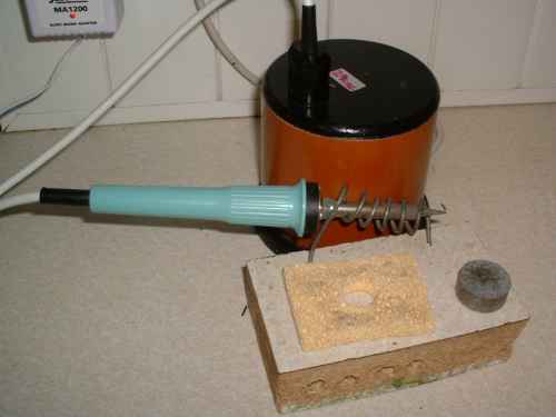
The finished product.
|
|
 - a friend of mine who has been in the hi-fi industry for a long time (name withheld to stall Interpol) recommends using a product known as TTC1 solder tip tinner and cleaner (Farnell code 419-631). This will help keep your soldering bits in good condition and is particularly useful if you use silver loaded solder which attacks tips more than standard type solders. A small tin should last hobbyists a lifetime and costs under 4UKP. You just wipe the tip of the iron across the powder to clean and wet it. - a friend of mine who has been in the hi-fi industry for a long time (name withheld to stall Interpol) recommends using a product known as TTC1 solder tip tinner and cleaner (Farnell code 419-631). This will help keep your soldering bits in good condition and is particularly useful if you use silver loaded solder which attacks tips more than standard type solders. A small tin should last hobbyists a lifetime and costs under 4UKP. You just wipe the tip of the iron across the powder to clean and wet it.
|
| Site menu
Page menu
|
|
|