|
Decibel Dungeon
|
|
OK, by now you may have guessed, I'm becoming addicted to Gaincloning! I thought that once my VBIGC was completed that I would switch off my soldering iron and take a long break from building amplifiers.
|
|
But I had this old Arcam A60 amplifier, one of my oldest bits of hi-fi which I purchased new back in 1981. It had done sterling service until it was replaced by two more A60's which I had modified extensively and used until I built my first Gainclone mono blocks. The old A60 had then been relegated to test duties, and somewhere along the line had done one test too many and as a result no longer worked. Now I could have spent some time and money fixing it but where's the fun in that, especially when I could just convert it to a Gainclone.
|
|
And so it was that I ordered yet another pair of the trusty LM3875 chips and some more 1000uF capacitors. I already had all the other components that were required, so it was a cheap conversion, almost certainly cheaper than repairing the original circuit!
|
|
As there had been much talk of the non-inverted Gainclone circuits recently, I decided to try out the following circuit.
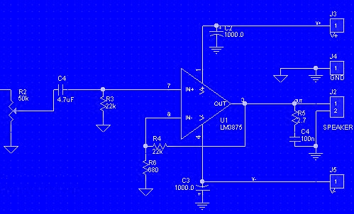
Non-inverted Gainclone circuit.
|
| Site menu
Page menu
|
|
|
I have had plenty of experience in stripping down the A60, both to repair them and modify them so it didn't take me very long to remove the large PCB. I then removed the back panel from the base and took it to my 'workshop' (a spare bedroom) to modify it so that I could install some phono sockets in place of the original DIN sockets. Having modified the aperture, I made up a small board which was bolted to the back plate. The board had holes to accept the phono sockets and a pair of the speaker terminals which I decided would be better placed on the other side of the heat sink such that there was a pair on either side of it.
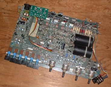
The PCB removed from the A60 carries all the circuits.
|
|
I then re-assembled both the front and rear panels onto the base plate and thought about how I was going to mount the new amplifier circuits. The A60 has a very shallow case so placing the chips vertically on the heat sink didn't really leave any room for point-to-point wiring. I decided to get around this by mounting the chips flat on a piece of aluminium bar and then screwing that to the bottom edge of the existing heat sink. This worked well and meant that I could stick to my tried and tested layout.
|
|
Very similar to my two previous GC circuits but this one is non-inverted..
|
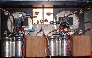
WARNING - if you skin caps like this, do make sure that they are not in contact with any other conductive material. If you do not understand this, please do not skin your caps.
|
|
By the way, the wooden 'blocks' are just housings for some home-brew caps. These are made from two skinned, non-polarized (electrolytic) caps which are connected in series. This configuration is said to reduce the distortion. I would still prefer a film cap in this position and will replace the current items when funds allow.
|
|
Turning my attention to the power supply, I already had the original transformer. However, I noticed that this was marked 27-0-27 and a quick calculation indicated that this would give rail voltages of plus and minus 38 volts, a bit near the maximum allowed for the LM3875. However, when I had built the rectifier bridge and measured the output, I had only plus and minus 35 volts. I can only assume that this old transformer was built to run from a higher mains voltage than we use now. I used some MUR860 diodes that I had in my parts box and a couple of 120uF caps which probably aren't strictly necessary but I had them there so I used them.
|
|
The next part of the job was to provide a volume control and input selector switch. Again, I looked in my parts box and found a 50K linear pot which I used with law faking resistors. I also found a rotary selector switch with four poles and three positions allowing me to switch both the signal and return inputs for each stereo channel. Both controls were mounted on a bracket made fairly quickly by bending a piece of perspex into an angle while heating it with a hot air gun.
The interior of the converted A60.
|
|
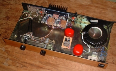
The front panel of the original A60 is quite cluttered with input selector buttons, volume, balance, treble and bass controls, on/off switch, headphone jack and LED. I decided to take a Shaker approach and just have the volume knob, selector knob and mains switch on view. A piece of cherry wood veneer was found and attached to the front panel. After gluing a piece of fibreglass board to the back of the front plate, I was able to drill the two holes for the volume control and selector switch.
|
|
The last modification was to the lid of the amplifier. The lids of the A60 have a tendency to bow in the middle. Because I had removed the PCB which had covered most of the base plate, it was possible to glue a short timber pillar to the lid, drill a hole in the base plate underneath where this wood is positioned, and then pull the lid down by screwing into the wood pillar.
|
| Site menu
Page menu
|
|
|
As mentioned above, I tested the output voltages of the PSU before connecting it up to the circuit. I then connected the PSU to the amplifier circuits and switched on.
|
|
Now, I have to make a confession here. I did something stupid and I'm only coming clean here in the hope that it may prevent somebody else doing the same thing.
|
|
When I skin the capacitors, I mark the polarity on the end of the cap before removing the 'skins'. On one of the caps, after removing the skin, I found that the marks I had made on the end of that capacitor were exactly 90 degrees out from each pin meaning that I could not work out which was positive and which was negative. I convinced myself that the + mark was nearer one leadout, designated that the positive leadout and proceeded to built the amp.
|
|
Fortunately, I was aware that I may have made a mistake here and before powering up, I placed some stout cardboard immediately behind the suspect capacitor. And it was just as well that I did as about 15 seconds after switching on (and standing well back) there was a loud bang, a lot of smoke and a very nasty smell!
|
|
But the worst was yet to come when I related this sorry tale to a friend who quickly pointed out that the capacitors have a longer leadout on the positive side and that I could still have identified the polarity instead of taking a chance. Of course, I knew that already which only made the whole incident more embarrassing!
|
|
With the damaged capacitor replaced, I powered up again and measured the DC offset on each channel. One channel measure 90mV and the other 75mV. I decided that this was a bit high and changed the 680 ohm resistor to ground with a 1K. This brought the offsets down to 55mV and 40mV which I am more happy with.
|
| Site menu
Page menu
|
|
|
By now I have come to expect something quite special from these little chip amplifiers and once again I was not disappointed. This time I have used just one 120VA transformer and a single rectifier bridge but the amount of bass produced by this amplifier is astounding! Clarity is one area definitely improved from the old Arcam circuit and the impression overall is that a new lease of life has been breathed into this 22 year old amplifier. A successful project, and given the small outlay, I am very satisfied with the result.
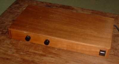
The small modifications to the case have brought the look right up to date!.
|
| Site menu
Page menu
|
|
|