Before you start FAQ.
Gainclone PSU FAQ.
Gainclone PSU building guide.
Gainclone Amplifier FAQ
General Gainclone FAQ
Gainclone Index.
Hung up on DIY hi-fi?
Then welcome to

The beginner's guide to building a Gainclone
(The information on this page pertains to building the simplest version of the Inverted Gainclone amplifier but most of it will be applicable to other chip amp designs)
Also see the GC PSU building guide.
Usual disclaimer applies.
![]()
![]()
Decibel Dungeon
Gainclone builders FAQ section
Before you start
Can anybody build a Gainclone?
In theory, yes, why not? I have come across a blind man on the forums who wanted to build one, albeit with some help obviously. Even if you have never built anything like this before, providing you have some soldering skills, and can follow instructions and a simple circuit diagram, you can build a GC.
Is it safe?
Doing just about anything in life involves some risk. If you don't look when crossing the road, it is probably more dangerous than building a Gainclone without care. Unless you use a battery power supply, you will be dealing with mains electricity, but providing you follow the instructions, and brush up on the safety aspects of using mains voltages, you shouldn't come to any more harm than the thousands of people who have successfully completed a GC.What tools do I need?
Rather than repeat myself, may I refer you to the Getting Started section of this site.
What skills do I need?
Again, please refer to the Getting Started section of this site.Is it honestly worth the trouble to build a GC?
Yes it is. Just ask the thousands (or is it tens of thousands now?) of people who have done so. But you should be aware of the most important factor affecting the sound quality of a Gainclone. That is the speakers that you will use with the GC, or more specifically, how easy it is for a GC to drive those speakers. The GC is not a muscle amplifier and part of its excellent sound quality comes from the fact that is isn't. Most of the disagreement over GC sound quality is down to people using them with different types of speakers. Use one with the right type of speaker and it will surprise you if you have only been used to commercial alternatives costing under 1000 pounds.
What is the best type of speaker to use with a GC?
The quick answer is something that presents an easy load to the GC. There are whole threads dedicated to this topic on the various GC, and Loudspeaker forums. Briefly, the speaker should be high efficiency although anything over 89 db seems to work well with those at 93 db+ working better. Horns are an obvious choice, single driver speakers using a higher efficiency driver are good, and I use efficient open baffles. A few folk have even managed to get GCs working with ESL loudspeakers.
The PSU section
What sort of mains cable should I use?
I think that it is best to use a separate cable connected to an IEC mains socket. If you want to add a fancy cable later, you don't need to re-open your amplifier case to fit it. It should go without saying that such a mains lead will have a standard mains plug on one end to fit your mains socket, and an IEC plug on the other end. In the UK, we refer to this sort of lead as a 'kettle lead'.
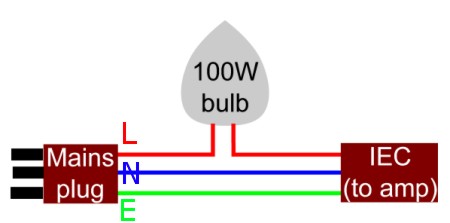
If you are making up your own mains lead it is vitally important that you understand which connector goes on at the amplifier end. So here is a picture with the correct item shown on the LEFT.
The correct connector to use on a mains lead.
In order to connect the mains lead to your amplifier, you will require an IEC socket as shown below.
 .
.
What sort of mains switch do I use?
Well, there are literally hundreds to choose from but the main decision is whether to use a single or double pole switch. What is the difference? A single pole will allow you to 'break' the 'live' wire from the mains. A double pole will allow you to 'break' both the 'live' and 'neutral' wires, not strictly necessary but an added safety feature.
You will see that apart from the single or double pole option there is also a single or double throw choice as well. You will need a single throw for the mains switch so look for SPST or DPST types of switch rated for your mains voltage.
You can buy illuminated switches that cost a bit more but I tend not to use anything that might pollute the mains supply by its operation and use a 'plain' variety.
What type of fuse do I use?
For most Gainclones using the transformers that I recommend below, use a 1.6AT (or 3.15AT if your mains voltage is 115/120 volts) fuse of a suitable size to fit in the fuse holder that you have bought. The 'T' in the specification indicates that the fuse will not blow for a set period of time. This is important for this part of the circuit as the transformer will draw a lot of current when it is switched on and that could blow an ordinary fuse. The 'T' types wait until the inrush of current is over and only blow if there is a fault after that. For this reason, this type of fuse is also known as an 'anti surge' type.
Fuses come in several different sizes but basically all work the same way. Just make sure that the size of fuse that you buy fits the fuse holder that you are going to use. I prefer the panel mount type of fuse holder that encloses the fuse and allows you to change it without having to open the case. I have just found out that there is a correct way to wire up this type of holder to avoid any possibility of electric shock when replacing the fuse! The supply from the mains must be connected to the tag on the end of the holder, and the supply from the fuse-holder should be taken from the tag on the side.
If you use a fuse holder that goes inside the case, try and get one with an insulating cover. Remember, this fuse will be carrying your full mains voltage and you won't want to risk touching it!
![]() - Make things easier for yourself with a combined IEC socket/switch and fuse holder as shown below. That way you only have a single hole to cut in your panel.
- Make things easier for yourself with a combined IEC socket/switch and fuse holder as shown below. That way you only have a single hole to cut in your panel.
How do I include an LED to show when the power is on?
I prefer not to use one but if you want to, this is how. You will need to know the If (mA) of the LED and it's Vf (voltage forward). The Vf for some LED's is given in the table below. Note that this is for 3 mm or 5 mm LEDs.
| Colour | Vf |
|---|---|
| UV | 3.3 |
| White | 3.3 |
| Amber | 1.7 |
| Orange | 1.7 |
| Red | 1.7 |
| Green | 3.3 |
| Blue | 3.3 |
The LED will need a resistor in series with it and to calculate the value of that resistor, the formula is:
(V-Vf)/If where V is the rail voltage supplying the LED.
Look in the suppliers catalogue to find If, and at the above table to find Vf. As an example lets say that you want to use a nice blue LED (Farnell order code 233-493) with a Vf of 3.3 volts and maximum If of 30mA and your voltage rail is 26 volts. So you would require a series resistor of the value
(26-3.3)/0.030 = 756
to run at maximum current. But it will be better to use the LED a bit lower than the maximum, say 20mA, so the resistor required will be
(26-3.3)/0.020 = 1135.
The nearest standard values to this is 1K2, although 1K would work OK too.
The series resistor can go before or after the LED, it makes no difference but should be rated at 0.5W or higher. The anode of the LED is connected to the positive rail and the cathode to the zero volt rail. NOTE - the LED is NOT connected to the mains input side of the transformer.
Circuit diagram for connecting LED to power rails.
An alternative method of powering an LED is described here.
Primary and secondary windings - which are which?
The primary side of the transformer is the side that connects to the mains supply at either 115-120 volts AC or 230-240 volts AC. The secondary side supplies the correct level of AC voltage such that when this is converted to DC voltage by the full bridge rectifier, that DC voltage is the correct level for the amplifier.
What transformer do I use?
You will need a transformer that:
- Works from your mains voltage, ie 115-120 volts AC or 230-240 volts AC. (Note, 10% either side of these figures doesn't matter).
- Supplies the correct DC voltage for the amplifier, ie between 20 and 38 volts DC (in the case of GC's using the LM chips - other chips may vary). Please note that the transformer secondary voltage quoted is NOT the voltage that you will get on the rails. You must multiply the voltage of the transformer secondary by 1.414 to get the actual voltage for the rails. (Please note that this figure is correct where a full rectifier bridge (like the one shown below) is used and there is no load. When the load is attached, voltage will drop by around a volt with a typical GC circuit).
- Supplies enough current for the amplifier. In the case of the Gainclone, I suggest a minimum of 120VA if you use just one transformer, or 80VA if you use one transformer for each channel.
You may of course use transformers rated much higher. 300VA or even 500VA have been used and will work. Some people claim that larger VA ratings work better than the smaller ones and this may be the case. The negative side of a larger transformer will be the cost and (larger) physical size. There will also be a higher inrush current when the amp is powered up. This may do nothing more than dim any lights in the room or it may produce (unwanted) sounds from your speakers.
How do I wire up the transformer?
This will depend on the wires that are attached to the transformer (if any). There will be either two or four primary leads (or solder tags) depending on whether the transformer has single or dual primaries. If you have just the two primary connections, you connect one to the 'live' wire from the mains (after the mains switch and fuse of course), and one to the 'neutral' wire (it doesn't make any difference which one goes to which). Sometimes there is an earth connection on the primary and this should be connected to the earth wire from the mains lead which in turn is bolted to the metal case.
Dual primaries allow the transformer to be used with either the lower (115-120) or higher (230-240) supplies. If your transformer has dual primaries, and you have a 115-120 volt mains supply, you pair up the wires to make just two connections to the mains supply. Which wires you pair together depends on the transformer but the four wires will be (or should be) identified as 0, 115, 0, 115. The two 115 wires are joined together and connected to the 'live' supply and the two 0 wires are joined and connected to the 'neutral' supply.
If you have the higher mains supply, one of the 115 and one of the 0 wires are joined together and insulated but connected only to each other. The other 115 wire is connected to the 'live' wire from the mains and the other 0 wire connected to the 'neutral' wire.
There may be three or four secondary wires on the transformer, depending on whether it has a single secondary winding, or dual secondary windings. To keep things simple, we will assume that one rectifier bridge is being used so:
With single secondaries (3 wires) two wires will be connected to the rectifier bridge (~) and one to the zero volt (0v) rail. Usually the two wires that go to the bridge will be the same colour and the 0v wire will be different.
With dual secondaries (4 wires), two wires will carry the secondary voltage and two wires will carry zero voltage. You will need to know which wire is which and this information should be supplied with the transformer. One zero volt wire and one of the wires carrying a secondary voltage are joined together and connected to the zero volt rail. The other two wires are connected to the rectifier bridge. If you buy a ready made bridge the connections for the wires from the transformer will probably be marked with the ~ symbol.
NOTE - it doesn't matter which of the two wires is connected to which part of the rectifier bridge. The rectifier bridge will convert the AC supply into a positive and negative DC supply.
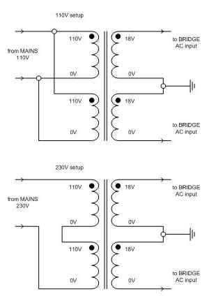
Wiring diagram showing a transformer with 18-0-18 secondaries connected for 110 volt or 230 volt mains supply (for a single rectifier bridge).
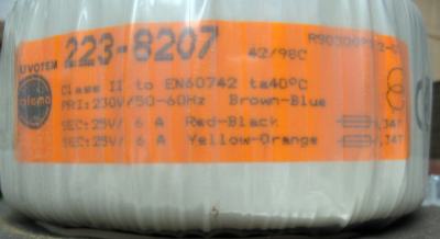
If you are lucky, you may find the wiring 'codes' on a label attached to the transformer (or on the packing box) like the one in the picture below.
![]() - If you have bought an Antrim transformer, you can find the correct method of wiring them up on the Antrim site.
- If you have bought an Antrim transformer, you can find the correct method of wiring them up on the Antrim site.
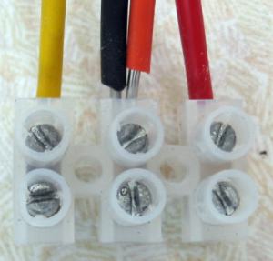
To use two rectifier bridges with one transformer, it must have twin secondary windings. You will know if it does have twin secondaries by the number of secondary leads (or terminals) as there will be four of them instead of three. If your transformer has twin secondaries, and you want to use a single rectifier bridge, two of the secondaries must be joined as shown in the picture below.
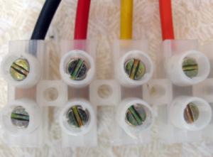
If using two rectifier bridges, the connections are kept separate as shown below.
What is best, a ready-built rectifier bridge or one built from discrete rectifier diodes?
You can find arguments for both actually. Some say that the diodes in ready-built bridges are more closely matched than individual diodes and are therefore superior. Others will point out that using individual diodes allows you to use better, (faster, soft recovery) diodes. For absolute beginners, a ready built bridge is one less part of the circuit to construct and get wrong. It will come with four connectors and clearly marked showing what wires to connect where. One rated at 15 amps or more will be more than adequate! Take your pick!
Which rectifier diodes to I use to build my own bridge?
Again, the choice is enormous but if you are a beginner, take advice from the more experienced. Read around the forums and see what others are using. I name my choice on my parts list page and it works well in my system. You can get away with the very cheapest types but for a little more cost you can have something much better so I suggest not skimping on these items!
How do I build a rectifier bridge?
A (full) rectifier bridge is built using four single rectifier diodes. All diodes have an anode and cathode connection and the cathode connection is usually indicated in some way like a silver band or a letter K. Some diodes also have the anode indicated by the letter A.
The diodes are connected as in the diagram below. It is not difficult to do this but always make sure that you have checked that you have the diodes connected correctly before you apply the power.
Circuit diagram of full discrete rectifier bridge.
You can build the rectifier bridges on strip board (probably the easiest way), hard-wire them on to any suitable material, or make small PCB's using copper-coated boards. It is possible to make a rectifier bridge PCB with just three cuts of a craft knife and a dozen drilled holes! WARNING - If making a PCB in this way, do make sure that you have cut right through the conductive copper coating and there are no nasty short circuits! To be sure, you can test the board with a multimeter.
A simple PCB to make a rectifier bridge using only a sharp knife and a drill.
But using stripboard is arguably the easiest method of making a rectifier bridge from discrete diodes. The picture below shows two rectifier bridges built onto a small piece of stripboard.
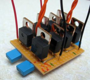
Apart from the diodes (four per bridge), the only other items required are two wire links (for each bridge) and the connecting wires. It is fairly safe to say that for a Gainclone heat sinks are not required for the rectifier diodes.
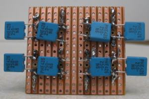
Only four breaks are required in the copper tracks which can be seen here between the legs of the small blue snubbing capacitors.
Should I use snubber capacitors on the rectifier bridge?
I prefer to as they are inexpensive and almost certainly don't make the sound any worse, and probably improve it. Use small types, ceramic or better and values of 0.022ufd are what I recommend. You connect them across each diode (or in the case of a bridge, across the terminals). Snubber capacitors are supposed to reduce the noise that the rectifier diodes make as they turn on and off.
Should I use fuses on the DC rails?
I would suggest using these at least to begin with. When you have your Gainclone working properly and have finished doing any modifications, then you could remove them (and replace them with a plain wire link). Note, while you use a slow-blow type of fuse on the primary side of the transformer, you should use the fast-blow type on the DC rails. This type of fuse often has a F suffix, eg 3.15AF is a fast-blow fuse rated at 3.15 amps. The value of the fuse should be as near to possible as:
The voltage rail divided by 0.707 divided by the impedance of your speakers
So if you have 27 volt rails and use 6 ohm speakers, that would be
(27/0.707) divided by 6 which is 6.36
Because the power is supplied from two (split) rails) each rail supplies half the power so we must divide the 6.36 by two to arrive at 3.18.
The nearest value is a 3.15 fuse in that case.
A Gainclone PSU.
NOTE, the fuse on the primary (mains) side of the transformer must be on the live lead and not the neutral!
What type of wire should I use?
On the primary side, I always use wires from the same cable that I use for the mains supply lead. On the secondary side I use 0.6mm solid core equipment wire, sticking to my colour coded system, ie red for positive supply, blue for ground connections, and black for negative supply.
Should I keep the PSU in a separate case?
Generally this is considered a better option. Keeping any alternating current (AC) well away from direct current (DC) is good practice as is keeping the magnetic field of a transformer well away from the amplifier circuit.
However, both the above requirements can be met using a single case for both PSU and amplifier, especially in the case of the Gainclone where smaller transformers can be used and the amplifier circuit is very compact. If you use a separate case, it will add to the cost with two cases needed instead of one, and an umbilical lead required to connect power from the PSU to the amplifier (the connectors are the expensive items here).
So it's up to you which system you use. I usually use a separate PSU but am about to build an 'all-in-one-box' type to keep costs down.
Obviously when you make one of these you should make sure there are no exposed conductive parts, so please don't just wire one up with bare wires.
You should also note that any capacitors used after the rectifier bridge must be rated at the rail voltage multiplied by 1.25. So if your rail voltages are say 36 volts, the capacitors must be rated at 45 volts. In this example, the nearest safe rating is 50 volts. Don't use lower rated capacitors, if they can't handle the voltage (and remember your mains voltage varies) they will explode! Remember, this applies to all the capacitors connected to the voltage rails of the GC!
The amplifier
Which chip should I use?
There is now quite a choice of audio power amplifier chips from several different manufacturers. Each chip has it's own 'fans' but probably the most widely used for building Gainclones is the LM3875 from National Semiconductor. If you are a beginner, then I suggest going with the LM3875 as you will find it easiest to get help and advice from the many who have who have already used it.
Should I use the insulated or uninsulated version?
It is always good practice to make sure that the chip (which is at -V) is insulated from the heat sink and it is essential if the heat sink is connected to the metal case which should be at earth. So you will need either the insulated version of the chip, or an insulating pad to go under the uninsulated chip (and insulating washer for the screw if used). See my parts list page for the pad that I used.
Always make sure that there are no sharp burrs on the heat sink that may pierce the insulating pad and cause a short circuit.
What sort of heat sink do I use?
The simple answer is anything that you can get hold of! The data sheets that the chip manufacturers supply give mathematical calculations for the recommended size of heat sink needed for the amount of power that the amplifier will be using. But, that's a bit beyond the 'beginner's' stage so what do you use? The first option is to use a heat sink from a defunct power amp if you have one. Any should do as the GC is not a big amplifier and should work OK with most heat sinks. Alternatively, find some aluminium strip, at least a quarter of an inch (6mm) thick (three eighths of an inch (10mm) would be better) and use that. I would recommend a piece at least 4 inches (100mm) by 2 inches (50mm) for one channel of a GC. Note, if you use supply rails above 30 VDC, you will need a larger heat sink!How do I mount the chip on the heat sink?
There are several ways to mount the chip on the heat sink. Probably the easiest way is to simply drill a hole of the correct size and use a suitable nut, bolt and washer. Alternatively, if the heat sink is thick enough and you have access to a suitably sized tap, drill and tap a hole and attach the chip with a bolt and washer. Some people prefer to use specially made spring clips that are screwed to the heat sink and go over the chip. These are said to give the chip a very good contact with the heat sink and increase the conductivity so that the chip stays cooler in use.
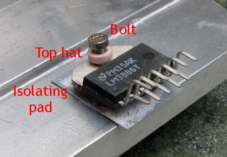
Remember it is best , if not essential, to isolate the chip from the heat sink! Most chips also come in an insulated package (eg LM3875TF) and this may seem like the easiest option to a beginner. However, the TF version does not work quite as well as the uninsulated LM3785 at keeping itself cool. To isolate the (uninsulated) chip from the heat sink, you can buy isolating pads that both (electrically) isolate the metal part from the chip for the heat sink, and help transfer the heat from the chip to the heat sink.
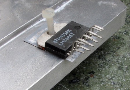
But be careful here, a common mistake is to use an isolating pad under the chip but a metal bolt to secure the chip to the heat sink. The metal bolt provides a short circuit, rendering the isolating pad useless! So ALWAYS either use a nylon bolt (second picture), or better still, what is known as a top hat (due to its shape), between the bolt and the chip (first picture).
 .
.
 .
.
Some isolating pads come with an extra bit to isolate the mounting bolt as you can see in the picture below.
 .
.
I have not used heat sink compound on any of the GC's that I've built and they have never run hot. Bit some people recommend compound as well as the isolator pad so, if in doubt use that too.
What type of capacitors should I use for the Gainclone?
There are two types used in the very basic GC circuit. The input capacitor through which the signal passes should be at least 2.2 micro farads (uF) in value, preferably 3.3 or 4.7 uF. Get the best quality that you can afford. Something from the Black Gate range is very good here.
The other type of capacitor used is for decoupling the power supply rails. 1000 uF types rated at 50 volts or above are recommended. Black Gates are good but expensive and many of us have had good results with the Panasonic FC types.
What type of resistors should I use for the Gainclone?
This is down to personal taste really, but here is what I prefer:
- For the input resistor - a carbon film type.
- For the feedback resistor - I use two Welwyn RC55's here. I like these resistors, they come in a very tight tolerance, and sound good. I use two in parallel to give a power rating of 0.5 watts as a higher rating is said to sound better for feedback use.
- For the output resistor (if used), a wire wound type with a power rating of at least 3 watts.
- Any other resistors can be standard 1% metal film types rated at 0.25W.
How do I connect it all together?
The choice here is to 'hard wire' or use a PCB that you can either make yourself or buy. Several people are offering PCB's for chip amps. Scott Nixon is one well-known source and supplied this information:
"I have pcbs for 1875 and 3875, inverted as well as normal. The layouts I use make grounding a piece of cake and greatly simplifies assembly. The only thing hard with my design is the mechanical fit to get holes to line up correctly. Just careful planning, trial fitting and marking. Then a +/- and ground to each board and the RCA is fed off the pcb."
Holland based Fedde Bouwman is also offering PCB's (and other bits) for Gainclone construction.
Another great source of kits, and based in the USA is Chipamp.com.
If you choose to 'hard wire', be very careful that wires don't touch each other (or other metal parts) and cause a short circuit. Where ever possible, sleeve exposed wires and lead outs with sleeving taken from scrap pieces of wire. After you have soldered components together, you should glue them in place with some hot melt glue to prevent them moving and breaking the fragile solder connection.
Possible back-panel layout of amplifier (one channel).
In what order should I assemble the parts of the amplifier.
I would suggest the following:
- Prepare a back panel on which is attached the heat sink, the loudspeaker terminals and the phono input socket (see above diagram). If using a separate PSU, the socket for connecting the power should be on this panel too.
- Remove the pins of the chip that are not connected to anything. These are marked as NC on the diagram of the chip. Be careful doing this - you cannot put them back if you make a mistake!
- Solder the feedback resistor(s) between pins 3 and 8. This is easier to do if you have the version of the LM3875 that has stepped pins (ask for it when ordering).
- Screw the chip to the heat sink with the insulation pad between the two.
- Trim the positive leadout on one of the 1000 uF/50v capacitors so that it can be placed as near as possible to the chip with the leadout connected to pin 1. Solder in place and glue it down.
- Sleeve the negative leadout of the above capacitor and solder it to the power ground star.
- Trim the negative leadout of the other 1000 uF/50v capacitor so that it can be placed as near as possible to the chip with the leadout connected to pin 4.
- Sleeve the positive leadout of the above capacitor and solder it to the power ground star.
- Trim the leadouts of the input resistor and input capacitor so that they fit between the phono socket and pin 8 of the chip. Add sleeving if necessary and solder them together, then to pin 8 of the chip, and lastly to the phono socket.
Please note, when using a polarised capacitor on the input, the positive (+) leadout is connected to the input and the negative (-) to the input resistor. - Solder the resistor from the phono input socket to the ground tag on the phono input socket. This ground tag is the signal star ground.
- Solder a (red) wire from the positive power connection to pin 1.
- Solder a (black) wire from the negative power connection to pin 4.
- Solder a (blue) wire from the zero volts power connection to the power ground star.
- Solder a 0.22uf capacitor across a 100ohm resistor and solder this between the earth connection of the power supply and the (metal) case. Solder a (blue) wire between the connection to the case and the power star ground.
- Solder a blue wire from pin 7 to signal star ground.
- Solder a (red) wire from pin 3 of the chip to the black speaker terminal.
- Solder a black wire from the red speaker terminal to the power star ground. (No I haven't got it round the wrong way. With an inverting amplifier we need to invert the phase again to get back to the original 'phase' and we do that by connecting the wires to the speaker terminals opposite to how they would normally go).
Note that the power star ground point should be kept as close as you can to the two decoupling capacitors and should not involve you having to add any length to the leadouts.
And that's all there is to building one channel of the most basic version of the inverted Gainclone amplifier! It should look something like the diagram below.
Internal layout of amplifier (one channel). Please note that the position of the power ground star should be as close as possible to the decoupling capacitors (not as shown here).
What's the big deal about the grounding arrangement?
To beginner's the grounding arrangement where some ground wires are taken to one point and others to another, and then those two points are joined together may seem a bit unnecessary. But there are valid reasons for doing the grounding in this way and I will offer you two explanations: a simple one and a technical one, both of which I hope will convince you of the importance of getting the grounding arrangement correct.
My simple explanation:
Let's use the water analogy! We want the signal as 'pure' as possible and we know the power is 'polluted'. So we want to keep the two separate as best we can.
So the idea is that the returns to the power ground star are returned to the main ground star in the PSU without getting into the signal ground star. Still with me?
In theory, the wire going from the power ground star to the main ground star should be thicker than the wire connecting the signal ground star to it. Thicker wire, less resistance, so the 'pollution' flows to the main ground star and not into the signal ground star where it could affect the signal.
A technical explanation provided by Ukram on the diyAudio forum:
The single point ground principle is explained in the chip data sheet. Basically you should not have big currents flowing in the signal ground, because ground wire has some small resistance that causes small voltage that is seen as an input signal.
To help you find the correct wiring for your Gainclone, simply click on one of the following:
- One transformer with a single rectifier bridge
- One transformer with a double rectifier bridge
- Two transformers with single rectifier bridges per channel
- Two transformers with double rectifier bridges per channel
What do I need to check before I plug in my speakers?
(Remember to check both channels!)
Fortunately, because most of the amplifier circuit is built on to the chip, there is not a lot to check for with a Gainclone. But do make sure that you go over this checklist before connect your speakers and powering up.
- With the power supply not connected to the amplifier circuit, check that you have the correct voltages on the PSU output.
- Even if you are fed up with checking, do one more check of your circuit against the circuit diagram. Make sure that the decoupling capacitors are connected with the correct polarity.
- Do a visual inspection of your wiring and make sure that there are no loose connections. Better still, use something like a toothpick to gently prod the various soldered connections and check that they are not loose.
- Check for any places where bare wires may be able to move and come in to contact with another conductive surface.
- Do not connect up your loudspeakers yet. Instead, connect a 10 ohm resistor across the speaker terminals. This is to measure the DC offset voltage at the terminals.
 - you will find it easier to have a couple of short lengths of wire with small (insulated) crocodile clips at either end. These will enable you to connect your multimeter to the 10 ohm resistor leaving both hands free.
- If the circuit is exposed (ie not inside a case), wear some safety goggles when you power up the amplifier.
Now, with the voltage range of your multimeter set to 200 volts, switch on the power to the amplifier and keep an eye on the meter reading. It should be zero. Turn the dial on the meter so that it is set to the next lower voltage range. If it does not indicate overload (OL), select the next voltage range down again. You should get down to the lowest range and see a reading (for the inverted Gainclone design described on this page) of around 28mV. If not, see the next question. - Do a quick visual check of the amplifier circuit and look for smoke (unlikely) or arcing between any metallic surfaces in close proximity to one another (there shouldn't be any if you followed the instructions about sleeving them).
- If the DC offset reading is OK and you can see no other problems, switch off the power, plug in your speakers, connect a source, eg CD player switch on again and enjoy some music played through your new creation. And well done!
The DC offset reading is more than 70mV, what shall I do?
Go back and do all the checks again. If you are using a separate PSU, make sure that any of the wires in the umbilical have not come loose. If one of the wires carrying the positive or negative voltages is disconnected you will get that voltage on the speaker terminals.
If you have checked everything very carefully and still can't find your problem, go on to one of the chip amp forums listed at the bottom of this page and ask for help. Do describe the circuit that you have used and the component values. It will be unlikely that somebody can't help you find the fault.
Should I use some sort of loudspeaker protection?
It's not a bad idea when using a new, or modified power amplifier, to think about some protection for your loudspeakers, especially if they are expensive or difficult to replace! The easiest way to do this is with a speaker protection module that comes as a kit from Quasar Electronics. Or, if you prefer a more DIY approach, take a look at this design from the ESP site. These devices will protect against the most common cause of speaker damage, ie DC on the output of the Gainclone.
General Questions
What parts will I need to build the inverted Gainclone?
Please refer to my 'shopping list'.
What skills do I need to build a Gainclone?
It will obviously help to have some idea of basic electronics theory although with so much information given on this and other sites, you could get away without any.
You will need to know how to solder so if you need help, see this section of Decibel Dungeon.
Some basic handicraft skills won't go amiss either but if you take time and care, even the least skillful person should be able to build a Gainclone amplifier, even if they can't construct their own case(s).
What tools will I need to build a Gainclone?
For this answer, let's assume that you are using ready-made cases. So the essentials are:
- A screwdriver with interchangeable tips
- A pair of wire cutters
- A sharp knife
- A pair of needle nosed pliers
- An electric drill and some drill bits
- A couple of small metal files
- A soldering iron, solder and possibly a desoldering pump
- A simple multi meter (to check component values, voltages and continuity)
- Some wire strippers
- Some hole punches for making larger holes in aluminium cases
- Some taps (for cutting internal threads)
- A small vice
- A hacksaw
- A magnifying glass
- A pair of tweezers
- A hot-melt glue gun and glue sticks
It all seems a bit beyond me, can I get a kit?
There are some places selling kits for making various versions of the Gainclone although I do not know of one supplying the inverted type. Quality Kits do one for the LM1875 chip, a lower powered version of the LM3875 (and several others as well).Can I buy I ready-made case?
Yes you can. Not everybody has the tools, skills or time to make their own cases. Obviously the options for cases vary according to where you live but here are a few suggestions.
- In the UK, Maplins, Farnell and RS do several suitable aluminium housings. Farnell and RS will also ship worldwide.
- More up-market are the housings from Ampbox if you want to give your GC a case to match the sound quality! Only one style available at present but more on the way apparently.
If you know of any other options, please let me know so that I can include them in the above list.
Do I need to worry about RFI?
It is a good idea to shield all parts of a hi-fi system from the increasing problem of RFI. Metal cases will do this job effectively and if you are using a non-metallic case, you can use aluminium or copper foil to line the case. Do make sure that and shielding material is connected to earth so that any signals intercepted by the shield will be conducted to earth by the earth connection, and NOT through the part of your hi-fi carrying the signal.
What is parallelling capacitors about?
Parallelling capacitors is using two or more capacitors instead of one. When these are placed in parallel with one another, their values are added together. For instance, if you use two 1000 uF capacitors in parallel, the capacitance through both of them is 2000 uF. But most often, capacitors are parallelled to enhance different parts of the frequency range. Some people doubt that this has any effect and some people even suggest reasons why this may be detrimental to sound quality! If you are building a Gainclone for the first time, I suggest not parallelling. You can always try it later if you want.
Can I increase the gain by changing the resistor values?
In theory, yes you can but as this is aimed at beginners, I would advise against this until you have got a working version with the suggested values. Some people have suggested increasing the gain by using a feedback resistor of between 250K and 300K improves the sound quality so you could try something between those values.
Can I reduce the DC offset to zero?
Yes you can. Around 28mV won't hurt your speakers but some argue that the lowest possible DC offset will improve the sound (and others that achieving 0mV is good practice). There are two methods to get close to zero volts DC offset. The first, suggested by Thorsten (designer of the inverted Gainclone) is to solder an 18K resistor between pin 7 of the chip and the signal star ground with a 22K resistor soldered between pin 8 and the signal star ground. This should reduce the DC offset to around zero but will depend on the component tolerances of your amp.
![]() - You could replace the 22K resistor with a 50K trim pot (trimmer) and adjust that until you get exactly zero mV.
- You could replace the 22K resistor with a 50K trim pot (trimmer) and adjust that until you get exactly zero mV.
The second method is to solder a resistor from pin 7 of the chip to the signal star ground with the value of this resistor matching that of the feedback resistor. I prefer the second method which sounds better on my GCs.
Do I need the 56K resistor between the input socket and ground?
If you do not include a pot (or attenuator) in your GC then you should have this resistor. It is there to make sure that the amp remains stable when there is no source connected. A value between 47K and 100K will do just as well.
Mikelm from the diyAudio forum explains a bit more fully:
"The answer to this depends on whether the GC is inverting or not. Either way you could do some damage to something.
Either way it would work fine without the resistor UNTIL you unplug the lead between the pre-amp and amp. With the lead unplugged the GC input would not be tied to earth.
For inverting mode this would mean the gain of the amp would become one and it would almost certainly oscillate. Even with a 100K resistor to earth the gain would still only be about 3 and may still oscillate so you may need a small cap across the resistor. perhaps 100pF. otherwise something could get VERY HOT
For non-inverting mode the input would no be referenced to ground so this and therefore the o/p will probably float up to quite a high DC voltage - enough to destroy a loudspeaker."
How do I include a pot (or attenuator) in the design?
Simply leave out the resistor between the input socket and ground and replace it with a pot or attenuator.
What type of volume control can I use with the Inverted Gainclone?
In case you haven't realised, the Gainclone is a power amplifier and if you do not build it with some means of controlling the volume, then you will need to use it with a pre amp. That pre amp could be just a volume control or could include some method of selecting the source. It could also contain circuitry for (pre)amplifying the signal or buffering it to cope with longer interconnects to the Gainclone.
The designer of this circuit suggested using a Linear potentiometer (pot) and a value of 10K seems to work best for me. For better sound quality a stepped attenuator is recommended and if you don't mind larger steps, a 12 way version can be constructed using a rotary switch and a pair of wafers.
Shunt attenuation (only four shunt resistors shown as example).
Thorsten has even suggested some resistor values to use with his design so here they are:
| Series resistor = 10K | ||
| Step# | Resistor | Db cut |
|---|---|---|
| 1 | 100 | 34 |
| 2 | 150 | 30 |
| 3 | 220 | 27 |
| 4 | 330 | 24 |
| 5 | 470 | 21 |
| 6 | 680 | 18 |
| 7 | 1K | 15 |
| 8 | 1K5 | 12 |
| 9 | 2K7 | 9 |
| 10 | 5K1 | 6 |
| 11 | 12K | 3 |
| 12 | 4M7 | 0 |
Use the make-before-break (also called 'shorting') type of wafers to make the attenuator (1 pole 12 way types). The series resistor is connected to the input and the wiper on the wafer. One end of the 'step' resistors are soldered to the tags on the wafers and the other to a wire that is connected to signal star ground. For more information on building a stepped attenuator click HERE.
Please note that in the case of the inverted Gainclone, the attenuator (or other type of volume control) forms part of the input loop. Because of this the values of the attenuator resistors (or pots) affect the gain of the amplifier and in some cases may cause it to perform outside it's operating limits! So, unless you know what you are doing, stick to the recommended values of resistor to build your attenuator.
If you want to buy a stepped attenuator kit at a really good price, take a look at this from Diyfidelity in Australia. They will ship anywhere at reasonable cost and this really does represent a good deal for an excellent attenuator. It's not mentioned on the site, but if you ask them, they do accept payment by Paypal, making the transaction much easier and faster!
I have a pot or stepped attenuator with different values to the ones mentioned above. Will this work?
Depending on the value of the pot/attenuator, it will work to a degree. That is to say that it will control the volume but probably not over the full-range. In some cases (and at some settings), it may also cause the inverted Gainclone to operate outside the limits it is designed to; so it is best for beginners to stick to one of the recommended values for their pot or attenuator.
I don't have a pre amp so how can I use my Gainclone?
A power amplifier needs some sort of preamplifier, either a passive type (with no gain stage or buffer) or an active type (with the gain stage or buffer). The passive preamplifier is obviously far simpler and in cases where you do not need to drive long interconnects to the power amplifier, it can be a better solution because there are far less components in the signal path. So, if you put the pre amp stage in the same housing as the Gainclone circuit (or very close to it) you can use a passive type which could consist of nothing more than the volume control discussed above.
In practice, most people require some method of listening to more than one source so you may need a method of selecting the source. That would consist of a number of phono sockets depending on how many source components you have, and a switch to enable you to select the source. For two sources, a simple DPDT switch will do, for more than two, the solution is a rotary wafer switch like the one recommended for building the attenuator, BUT using non-shorting, or break-before-make type wafers. For further details see HERE.
The signal is taken from the input socket to a solder tab on the switch wafer. From the single solder tab on the other side of the wafer, the signal is taken to the volume control. The ground connection is taken from the input socket direct to the signal star ground point although you can join all the input grounds together and use just one wire to the signal star ground.
This diagram shows the wiring for a simple preamplifier section for the Gainclone. Just one channel is shown (with four inputs) for clarity, and the attenuator is shown with just some of it's resistors to ground. If using a potentiometer, it goes in place of the attenuator.
Do I need the 0.22 ohm resistor on the output?
There is no definitive answer to this question. Most people try building a GC without the 0.22R resistor on the output (particularly those building the minimised versions). If there are problems, then adding the resistor is one possibility for curing them. Basically, this question is 'system dependent', ie it depends on which speakers and cables you use.
Do I need the Zobel network on the output?
As with the 0.22R output resistor, the effect of the Zobel network will vary according to the system that the GC is used in. However, after leaving it out originally, I can now say, through careful testing, that I would recommend the inclusion of the Zobel which should improve the bass performance particularly.
Why do I get strange sounds after I switch off the power?
This is either caused by poor quality decoupling capacitors or by oscillation. If you have used cheapo decoupling caps, try replacing them with something better. If the problem persists then ask for help on one of the forums.
Which is the best version of the Gainclone?
There are builders who prefer the NIGC and those who shout for the IGC. In my opinion there is not a 'better' one, rather they sound very much alike and it is down to personal preference and system matching as to which one you finally choose.
What I do suggest is that you build one of the basic versions, listen to that and then try the variations.
How do I calculate the gain of a GC?
This depends if you are building the inverted, or non-inverted design! For the non-inverted GC (in the diagram below), the gain is calculated by the formula (R1 + R2)/R2. Rin sets the input impedance!
How much power does a Gainclone put out?
This will depend on the power supply that you build for it but as a rule the LM3875 can put out around 40 watts per channel.
However, power output is one of those specifications that is often quite meaningless. If you have horn speakers, you will only need a couple of watts anyway, and efficient speakers will go louder than you want with most GC's.
If you need more power (and don't assume that you will), you can try bridged versions of the GC but these are not really for beginners. So once again, the advice is to start off by building one of the basic versions first.
Will the GC work with my speakers?
It is likely that a GC will work with almost any loudspeaker but it is almost impossible to predict how well the combination will produce sound together. It was originally thought that the GC only worked well with high-efficiency speakers but this has been disproved. I have even heard glowing reports of a GC used with Martin Logan electrostatic speakers.
Are there any speakers, DIY or commercial that work particularly well with the GC?
Not to my knowledge. If you want to build or buy speakers specifically to partner a GC, the best thing to do is surf the net and read about the experiences of other GC users. The hi-fi forums are a great place to find out this sort of information.
Can the GC's be used in an active speaker system?
Yes they can and due to their simplicity and low cost, they are an ideal candidate for the job.
If you are using the amps some way from the crossovers, I suggest using the NIGC version otherwise the long interconnects will affect the performance of the inverted versions (unless they are buffered).
What is the difference between insulated chips and uninsulated versions?
The uninsulated chip (T suffix) requires that you use an insulation pad and plastic washer to keep the chip isolated from the heat sink. The other is already insulated and just screws/bolts to the heat sink as it is.
The insulated (TF suffix) version is reported to not transfer its heat to the heat sink so efficiently as the non-insulated version. But in practice, this shouldn't be an issue.
The only time I would be worried about the temperature with a Gainclone, is when using the regulated power supply that appears to make the chips run at a higher temperature.
How does the sound of the Gainclone compare to XXXX amplifier.
This is a question that I often get asked through the web site. Basically there is only one sure way to find out and that is to audition them both together. What I will say is that the GC is a very good amplifier and will out-perform many expensive commercial amplifiers if it is built and used correctly.
Why does the GC perform so well?
If you can find an answer to this question, let me in on the secret!
A friend of mine, a commercial hi-fi designer by trade, finally took the plunge and built a GC after listening to me raving about them for months. He was astonished at the sound quality but could not offer an explanation despite his expertise and many years of experience!
Is it really worthwhile?
From my own experience, I would say yes, most definitely. But don't take my word for it, read this review of Peter Daniel's GC and then decide for yourself!
I have another question what shall I do?
Click HERE and ask me. Or visit one of these forums:
DIYAudio forum.
diyhi-fi.org forum.
and ask for help. But please do make sure that your question has not already been answered, either here or on the forums before you ask.
For further help, check out the main Gainclone page and my 'Getting started' page as well.
Thanks also to the following for their contributions to the above:
- John Cheadle
- Martin Melhus
- Brian Phillips
- Richard Hallman
- Moamps
- Music Machine
- Mark Hennessy
- Oscar Järkvik
- Mikelm
Please note, the information on this page is provided in good faith and is correct as far as I can tell. However, no responsibility is taken for consequences arising from the use of the information. The usual warning applies; working with mains electricity can be dangerous, if you are not confident in what you are doing, don't take chances.
Last update: 9th November 2016 - Copyright © 2003-2009 - Author Nick Whetstone