Hung up on DIY hi-fi?
Then welcome to

Building an *active* pre amp for Gainclones.
Click here for a simple discrete Jfet pre-amp with gain.
![]()
![]()
Decibel Dungeon
Introduction.
There is little doubt (IMHO) that the inverted Gainclone works better when used with either a buffer or a pre amp. I have written about my buffered Gainclones so I am adding this page on how to build a pre amp to go with a Gainclone.
A block diagram of the pre amp.
The housing.
Well, we may as well start with the case as it will dictate what goes where and if it will all fit inside. I'm going to be describing the pre amp that I built and you can see that the case is home-made (to match my GC mono blocks).
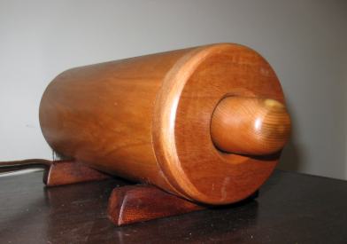
My GC pre amp to match my GC mono blocks.
The PSU (part 1).
OK, let's get the PSU out of the way first as it is quite important. Based on experience, I strongly recommend a dual regulated power supply for a pre amp. Recently I tried using the buffer circuit that I have chosen for this pre amp project with one and two stages of regulation and I could clearly hear the improvement that having a second stage makes.
IMPORTANT
If you do not fit the components recommended below, make sure that the alternatives are safely rated. All capacitors must be rated at a minimum of 35 volts DC or above. The resistors between the transformer and rectifier must be rated at 5 watts or above. The other resistors must be rated at .125 watts or above.
Use a length of flexible mains cable or make your own by plating together three lengths of insulated wire and enclosing them in some heat shrink tubing.
A - Fuse holder and fuse
Use an open type fuse holder with a cover (Maplin codes KU30H and VJ57M) and an anti-surge fuse rated at 1 amp (Maplin code GL91Y).
Depending on the type of case you use and your skills/tools, it may be easier to fit a switch requiring a circular aperture (140-621) rather than rectangular (157-788).
I prefer toroidal type transformers, others prefer laminated and someone I know who has a lot of experience upgrading hi-fi swears by C-core types. For this project I recommend the Antrim brand toroidal transformer supplied by Maplin, code number DH59P. Antrim transformers are one of the better quality brands of toroidal transformers.
The rectifier transforms AC to DC. A silicon rectifier is a semi-conductor, only letting current go through it when the output voltage is more than 0,5 Volt below the input. At that very moment it switches "ON". Inside a semiconductor there is a capacitance as well. This capacitor, together with the inductance of the wiring, causes a very sharp peak voltage to occur. This peak is too fast to be dampened by the connected (electrolytic) capacitors.
The solution is simple, put a resistor between the transformer and the rectifier. The value is not absolutely critical but I suggest for a pre amp supply, a value of 10 ohms and rated at 5 watts (987-580)
Four rectifier diodes form the bridge rectifier which converts the electrical supply from alternating current to direct current. Note, that at the same time the rectifying stage changes the voltage by a factor of 1.414. I am currently using ultra-fast soft recovery diodes (367-357) which perform better than the standard equivalents.
The smoothing (or reservoir) capacitors store the electrical power (when there is a lower demand by the equipment) and release it at times when there is a large demand. A good compromise between performance and cost is to use the types made by BHC Aerovox. 4700 micro farads (536-192) is sufficient for this pre amp supply.
The large value smoothing capacitors should be bypassed with smaller values. I have used 4.7ufd polypropylene's, part number JY82D from Maplin which are in turn bypassed by 1ufd (286-916), 0.1ufd (286-886) and 0.01ufd (106-780) polypropylene's.
0.1ufd=100nf.
0.01ufd=10nf or 10,000 pf.
As their name suggests, these devices regulate the voltage supply. Start off with the standard LM317 (412-132) and LM337 type (412-223). There are more exotic and costly regulators but I have not yet tried them.
 Make sure that you connect the regulators correctly as their pin arrangement differs. Looking at the LM337 from the front, the pins are (from left to right) Adj, vIn and vOut. The LM317 viewed from the front also has the Adj pin to the left but followed by vOut and vIn.
The LM317/337 regulators are adjustable types which need to have their output set using a voltage divider consisting of two resistors. The output of this power supply is to be + or- 18 volts so, starting with a UAR value of 220 ohms (513-866) we can calculate from the formula
Vout = 1.25*(UAR+LAR)/UAR
that the LAR value should be 3K (514-135).
LAR - lower arm resistor (P).
UAR - upper arm resistor (N).
Vout - output voltage.
Please note, if you intend to use the discrete regulators described later on, you should set the voltage output of the first stage of regulation to +/-21 volts. That is achieved with a UAR of 220R and LAR of 3K6.
Q - 100 nF capacitors (2 off)These capacitors are to filter off any unwanted AC components on the voltage rails by allowing them to pass to ground via the 0 volt rail.
This will provide the means of connecting the psu to the pre amp. The items I use (149-325 & 149-322) are designated 'for audio' in the Farnell catalogue but are rated high enough for this job.
You could make up a PCB from a sheet of copper clad board but I suggest gluing (hot melt glue is ideal) the components to a suitable board (I use a 3mm thick piece of fibreglass) and then hard wiring them together.
I'll leave this up to you but I prefer to build my own. Remember, if you use a metal casing, it must be earthed (point Q in the diagram).
You will also need some insulated terminals (to connect wiring to the fuse-holder and mains switch), a terminal block, a cable gland and some method of securing the mains lead where it enters the casing. As these items will depend on your type of casing I cannot make specific recommendations.
- (Before you install the transformer) Take some thin enamelled copper winding wire and wind about 25-28 turns around the (toroidal)transformer. Make sure that you leave enough free wire to reach your LED location.
- Add a bit of tape to secure the wire to the side of the transformer.
- Carefully scrape off the enamel from each end of the wire using a sharp craft knife or similar.
- When you have built and tested the PSU, connect your multimeter to each end of the enamelled wire and you should (hopefully) find that there is a reading of 1.5 to 2 volts. Remember that this is AC so set your meter accordingly.
- If the voltage is around 1.5 to 2 volts (most LED's operate around that voltage but not all!), remove power and connect the wire ends to each leg of the LED (polarity doesn't matter with AC).
- Power up again and you should see your LED light up.
The PSU (part 2).
The discrete method.
I hope that you enjoyed the commercial break and got yourself a beer from the fridge! Don't worry, this part of the PSU is much less work so sit back and find out how you too can enjoy the benefits of a discrete regulator.
The negative and positive discrete regulators courtesy of Andrew Rothwell.
(for the positive regulator):
R8 and C4 form a low-pass filter at the input with a pole at 12.5 Hz. After that filter, the regulator circuit begins. R7 sets the source current for Q4. Q3 is simply a pass transistor. The Voltage drop over R5 is given by the voltage drop over the LED (which is constant at 1.7 V and therefore acts as a voltage reference) and Vbe (which normally is 0.65 V). As a result, the voltage drop over R5 is also constant. The output voltage is then regulated via R6 and R5, forming a voltage divider. The output voltage can therefore easily be calculated as
Vout = (Vd + Vbe)*(R6+R5)/R6 = 2.35 * (R6+R5)/R6.
C3 together with R6 make up another low-pass filter with a pole at 145 Hz.
The analysis seems to be ok, as I get an output voltage of 15.28 V according to the above equation using the values for R1 and R2 in the schematic above.
Mick has also kindly redrawn the circuit diagrams for the discrete regulators which you can see here.
The 'easy' method.
The easy way to make the second stage of regulation is simply to copy the first stage using the LM317/337 regulators.![]() - it is recommended that when using the regulators with opamp circuits, it is best to keep the regulators as close as is practical to the opamps voltage supply pins.
- it is recommended that when using the regulators with opamp circuits, it is best to keep the regulators as close as is practical to the opamps voltage supply pins.
The buffer.
After all your hard work building the PSU, I am going to make the buffer section very easy. And in this case, 'easy' doesn't mean compromising sound quality! You could put any buffer circuit in this position; I have shown a few options on the Buffered Gainclone page, but I have chosen the buffer that, to my ears sounds the best.
The simple discrete buffer courtesy of Andrew Rothwell and based on an idea by Les Sage.
- All three transistors are NPN types and choice is not too critical. The originator of this circuit, the late Les Sage, suggested using BFQ232 transistors that are available from Cricklewood Electronics (in the UK).
I have used BC547C transistors for Q1 and Q3 and ZTX653 for Q2. This choice was based on what I actually had in my parts box at the time.
 - be careful when soldering in transistors not to overheat them with the soldering iron. It is good practice to use a heat sink which clips to the legs of the transistor while it is being soldered. The heat sink looks like a pair of tweezers. Of course, if you use sockets, this is not an issue.
As stated above, if you use transistor sockets (Farnell part number 177-128), auditioning different types of transistor will be very easy.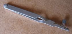
Transistor heat sink (click on image for larger picture) - The resistors are all 1% metal film types. The 100K values can be anything from 91K-270K. The 68R can be anything from 68R-82R. But stick to the 27K and 120R values as they are critical to the proper operation of the circuit.
- The output (DC blocking) cap can be anything you like that is between 2 uF and 4.7 uF. A polypropylene film cap is probably the best option.
This discrete circuit out-performs the opamp circuits that I have tried to date. The trade-off is that there is an unavoidably high DC offset (around 670mV in my case) so the DC blocking cap is a must, not an option! - The supply voltage can range from +/-15 volts to +/-21 volts.

Note, it is important to put the transistors in the correct way or the circuit will not work and you will probably damage the transistors. Transistors of this type have an emitter (e), a base (b) and a collector (c). Which ever transistors you use, you will need to know which leadouts are which. You can usually find this information somewhere on the internet or in the electronics suppliers' catalogues. In the case of the BC547 and ZTX653, the wiring is e b c as you look at the transistor while it is lying face down.
![]() - If you are not sure about the pins on a transistor that you wish to use, test the transistor in your multimeter. Most DMM's have a test facility and will only give a readout when the transistor is inserted the correct way.
- If you are not sure about the pins on a transistor that you wish to use, test the transistor in your multimeter. Most DMM's have a test facility and will only give a readout when the transistor is inserted the correct way.
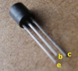
Transistor pinout details for BC547 and ZTX 653.
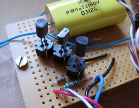
The buffer, so compact it will hardly take any more room than an opamp buffer. The transistors simply plug in to the sockets so you can try different types without the use of a soldering iron.
Update 3rd June 2005
It may be necessary in some cases to add a 1uF (film) cap together with a 1K resistor (in series) between the output of the pot/attenuator and the input of the buffer. If you have problems with noise when you use the volume control, try this mod.Source selector (for beginners).
Some people only ever use one source, usually CD but if you use more than one source then you will want to be able to select between each of those sources. This is most often done using some sort of switch. There is a much more complicated method using relays that I will leave for another time.
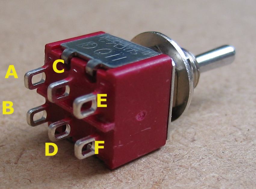
DPDT selector switch (click on image for larger picture)
Wiring A="Left channel source 1, B right channel source 1, C left channel out, D right channel out, E left channel source 2, F right channel source 2.
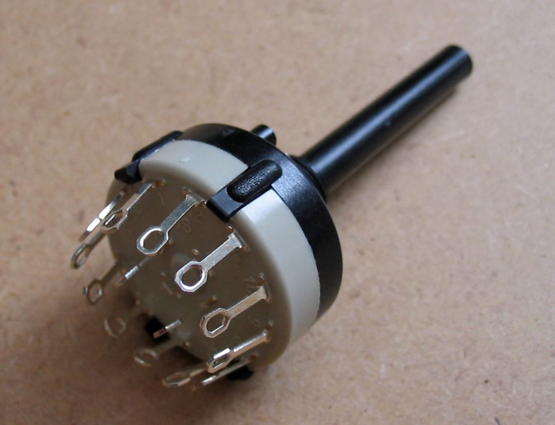
Rotary selector switch (click on image for larger picture)
Wiring depends on switch type
Volume control.
Pots
The volume control can be a simple potentiometer (better known as a pot) or a stepped attenuator. We will take a look at pots first.
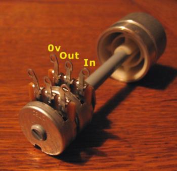
A typical stereo pot showing the connections. The law-fake resistor is soldered between the 'out' and '0v' pins.
Stepped attenuators
The main argument against stepped attenuators has always been their higher cost when compared to a pot. However, this needn't be a problem if you make your own attenuator, and this is not a particularly difficult job. The first problem is to find a suitable switch and this is probably the most difficult part of a DIY attenuator project!
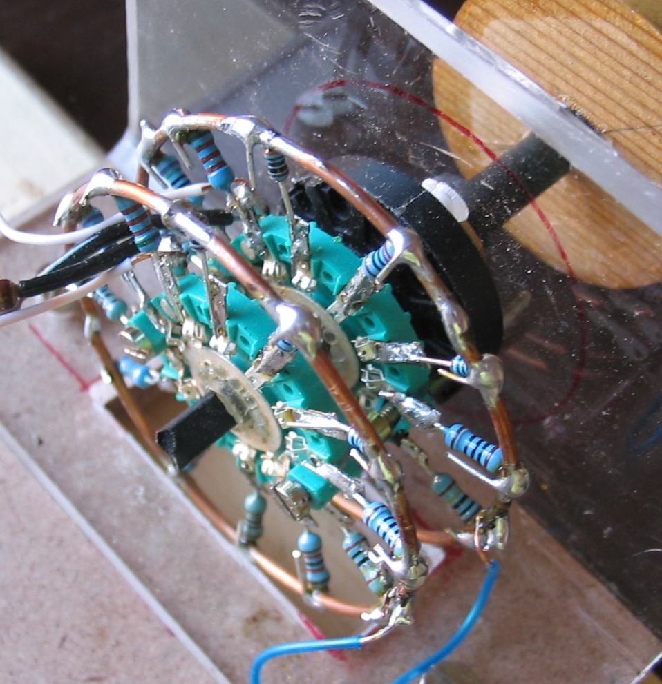
Home-brew attenuator (click on image for larger picture)
| Series resistor = 10K | ||
| Step# | Resistor | Db cut |
|---|---|---|
| 1 | 100 | 34 |
| 2 | 150 | 30 |
| 3 | 220 | 27 |
| 4 | 330 | 24 |
| 5 | 470 | 21 |
| 6 | 680 | 18 |
| 7 | 1K | 15 |
| 8 | 1K5 | 12 |
| 9 | 2K7 | 9 |
| 10 | 5K1 | 6 |
| 11 | 12K | 3 |
| 12 | 4M7 | 0 |
- Assemble the wafers onto the switch mechanism.
The switch mechanism has an adjustable stop so make sure that it is set so that you have a full 12 positions available.
Make sure that you place the switch wafers the same way around and also ensure that the same position is selected on both wafers. - Find the 'starting' position of the wafers by turning the shaft anti-clockwise until it can not go any further, ie it comes up against the adjustable stop. Now, using your multimeter, check which tab on the wafer is connected to the input tab on the opposite face of the wafer. Mark this tab with a pen.
- I suggest cutting one leadout of all the resistors to about a quarter of an inch (6mm). Leave the other end intact for now.
- Solder the short end of the lowest value resistor (100R in this case) to the tab that you have just marked. The resistor should form a straight line with the centre of the wafer and the solder tag.
- Continue soldering all the resistors to the tabs of the first wafer in a clockwise direction (when looking from the shaft side of the wafer).
- Take a piece of copper wire (0.8mm to 1mm diameter) and remove any insulation. The wire should be about six inches (300 mm) in length.
- Find something circular about 2 inches (50 mm) in diameter that you can use as a former. Form the copper wire into a neat circle, trim the ends and solder them together.
- Place the attenuator into something like a vice (or a hole drilled into a piece of wood) so that the wafer is horizontal. Place the copper wire circle over the resistor ends so that it is centrally positioned in relation to the wafer. Carefully fold the leadout of one resistor over the copper wire making sure that you don't reposition the copper ring. Do the same with the resistor on the opposite side of the circle and then the two resistors between these two. And so on until the wire ring is securely held in place. Then trim the excess leadouts and solder all connections.
- Repeat the above steps for the second wafer.
- Solder the input resistors to the single tabs on the wafers together with the wires that will connect to the buffer input.
- Solder a wire to each wire ring. These wires will go to the ground connection of the buffer.
![]() - If you use anything with a greater tolerance than 1%, I suggest that you sit down with a meter and measure the resistors to get the closest match as possible. Remember, keeping both channels as close as possible is very important!
- If you use anything with a greater tolerance than 1%, I suggest that you sit down with a meter and measure the resistors to get the closest match as possible. Remember, keeping both channels as close as possible is very important!
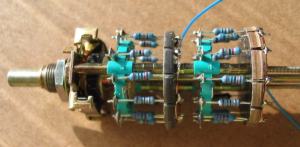
Another version of the DIY attenuator.
Wiring it all together.
When you have built your PSU and extra regulator section, the buffer and attenuator, install all the necessary sockets into your case. You can then wire it all together to make a working active pre amp.
Pre amp wiring diagram shown for just one channel. This also assumes that you do not switch the 'cold' line from the input.
Note that you need two buffers to make a stereo pre amp. You can use either one set (neg and pos) of regulators for both channels, or one set for each channel.
Testing.
I recommend the following tests:- Measure the output of the transformer secondaries before you connect it to the rectifier bridge.
- Measure the voltage after the rectifier bridge. You measure the voltage between each DC output of the rectifier bridge and the zero volt rail.
- Measure the voltage at the output of the first stage of the PSU, ie before the regulator circuits.
- Measure the voltages on the outputs of the regulators. They should read +15 VDC for the positive regulator and -15VDC for the negative regulator.
- With the buffer powered up, measure each rail voltage (should be +/-15VDC.)
- Check the DC offset at the output of the buffer. It should be very close to 0mV.
Last update: 29th July 2006 - Copyright © 2004-2006 - Author Nick Whetstone