Hung up on DIY hi-fi?
Then welcome to

Building a Jfet *active* pre amp for Gainclones with gain.
![]()
![]()
Decibel Dungeon
Introduction.
I had a lot of interest in the pre-amp design that I posted on Decibel Dungeon. One question often asked regarding the simple three-transistor buffer has been 'can it have some gain?' Well, I don't know how to alter that circuit to give it some gain but I can now publish another simple circuit design, this time using a single Jfet, and one that does allow for adding some gain.
The design.
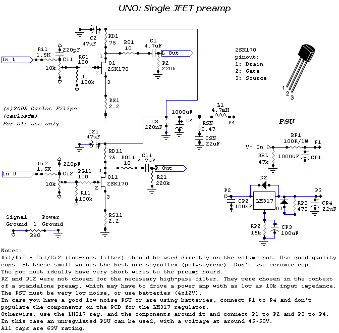
The main circuits - words and drawings by CFM. Please note the CSN is a standard electrolytic type, not a non-polarised type.
The circuit for the PSU.
- Note that to get the 47 volts we use both sections of an 18-0-18 volt transformer to get 36 volts prior to the rectifier bridge. We chose this because it is not easy to source a 35 VAC transformer with a low current rating!
- After the bridge we get approximately 50 volts and then loose a few volts across the resistors.
- The rectifier bridge can be made up from separate diodes or you can use a ready-made variety. This supply won't draw a lot of current but the bridge must handle the voltage.
- The 20K resistor across the rails is to drain the capacitors of charge when the power is turned of. I used a 3 watt rated resistor but 1 watt is probably adequate.
- The 2R2 resistor, 2200 uF cap, 10R resistor and 10,000 uF cap make up what is known as an RCRC filter to smooth the power supply. The resistors should be rated at 1 watt and the capacitors (in fact all capacitors for this project) rated at 63 volts of higher.
- Don't forget the mains fuse.
- For connecting this circuit to the one in the pre-amp, ie the LM317 circuit, use either tightly twisted wires or screened cabled to avoid picking up any noise. This is important!
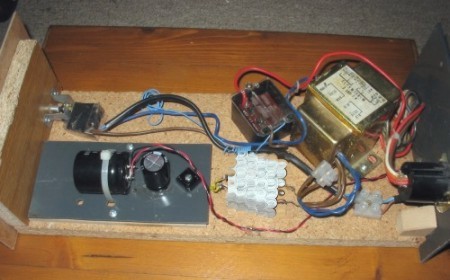
Simple but effective. I was lucky enough to have that transformer lying around!
The results.
Well, I have to admit to making a couple of mistakes along the way when I tried this pre-amp. But basically, if you take your time, it is not a difficult circuit to build. Indeed, with it's single rail power supply, it should be easier for beginners to follow! Make sure that you keep the two types of ground connections separated by the 1R resistor and of course, check that you insert the Jfets, the right way.
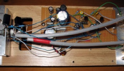
This simple circuit will easily fit inside one of the DD pods.
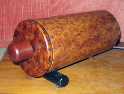
Another pre-amp, another pod! Many thanks to Carlos for sharing this design with us all.
This pre amp should work equally well with class-T amps or most other power amps for that matter!
Here are some answers to questions raised about the Uno pre-amp.
- Q. I have built the UNO and find the gain too much. How do I lower the gain?
A. Increasing the value of the source resistor (RS1 and RS11) lowers the gain. - Q. What is the usable DC voltage range for the UNO ?
A. Between 30V to 40V regulated. - Q. Will the transparency be improved with a different voltage ?
A. I don't think so. But the input filter (before the volume pot) can be reduced or even removed. If you want to keep a gentle RF filter there that doesn't impact the sound, then I suggest 51R + 100pF. - If my amp has an input capacitor, can I remove the output caps (C1) in the pre ? The amp has an input cap of 3.3 uF.
Yes, in that case the cap (C1 and C11) can be removed. But never forget that your pre amp has tens of DC voltage on the output. In case you connect it to a power amp without an input coupling cap. (!)
Last update: 14th September 2008 - Copyright © 2008 - Author Nick Whetstone