|
Decibel Dungeon
|
|
|
|
Having successfully built some Gainclone monoblocks, I wanted to try adding a buffer. As the confined space in the monoblocks made adding anything virtually impossible, I decided to build a second GC project that could be used to test the buffer option.
|
|
I chose to build a dual mono amp but housed in one case. At present the amp is just built onto a back plate which is screwed to a plank of wood. This makes access to the circuit quite straight forward for any modifications. I am using existing power supplies (one per channel) originally built for the monoblocks. Again, as a temporary measure, these are connected to temporary sockets on the amp but I may include the PSUs in the finished version.
|
|
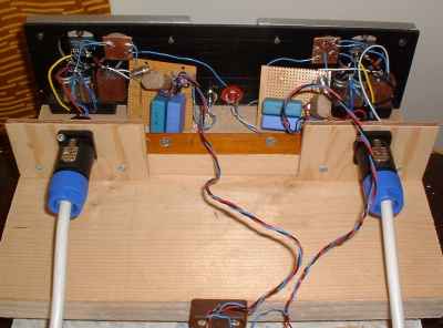
My MKII Gainclone circuit built on a plank of wood.
|
|
I have stuck fairly closely to the circuit used for the monoblocks with the following changes:
- The feedback resistance is now 254K (216 in the monoblocks)
- The input capacitor is 6uF (47uF in the monoblocks)
- There are no 0.1uF bypass capacitors on the decoupling capacitors
|
|
One other change is the use of slightly bigger heatsinks which are also separated from the back panel by 5mm. This allows air to flow over both sides of the heatsinks and the chip and I have noticed that this does improve the cooling quite significantly. With the monoblocks, the 36VDC PSU caused them to run a bit too hot on occasions whereas the 'new' GC runs without getting hot at all.
|
| Site menu
Page menu
|
|
|
As I said, the amp is not really fully built yet so construction time was much less than with the monoblocks. I have used some of the plastic covered fibreglass board that I like so much and mounted the heatsinks on the back. The chip is screwed to the heatsink through a cut out in the fibreglass and the other items are hard-wired to the chip, and then glued in place with hot-melt glue. The back plate is temporarily screwed to a plank of wood that also holds the connectors for the power supply. I have not included a volume control on this board but use one of my 'pots-in-a-box' (100K) in its own housing.
|
|
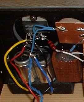
My MKII Gainclone circuit with P2P construction.
|
WARNING - if you skin caps like this, do make sure that they are not in contact with any other conductive material. If you do not understand this, please do not skin your caps.
|
| Site menu
Page menu
|
|
|
I actually thought this amp sounded not quite as good as my monoblocks when I first powered it up. Was this due to my expectations? Since listening to the Inverted Gainclone sound, I have come to expect quite a lot whereas, with the first ones, I would have just been happy that they worked! I think that the main difference would have been due to the input (DC blocking) capacitor which was a brand new home-brew (experiment) rather than the extremely good (and burned in) Black Gate NXQ's used in the monoblocks. However, I am not talking vast differences here and the dual mono GC still sounded extremely good.
|
| Site menu
Page menu
|
|
|
|
|
I have been a regular visitor to the chip amp forums for the last six months and follow each and every thread with interest. I have been particularly interested in the idea of adding a buffer and LPF to the IGC, something that has been successfully implemented by Joe Rasmussen (who suggested the idea originally I believe) with a valve buffer, and Pedja Rogic with his J-FET design. Both reported an improvement over the IGC in its 'basic' form and I wanted to try the idea myself.
|
LPF - stands for Low Pass Filter. This is a filter which blocks higher frequencies but allows lower frequencies to pass. The range of frequencies affected depends on the value of the components used.
|
|
My experience with valves is still very limited and I am in fact still perfecting my valve preamplifier. Pedja's J-FET buffer looked good but I couldn't find the items that he used available in the UK. And anyway, I had some buffers already built so why not use them, at least as a first step! The buffers previously did duty in a pre amp to buffer the tape output and are based around the OPA627 IC. All I needed to do was change the DC blocking caps on the outputs and then add the LPF components.
|
|
The OPA627 buffer circuit with LPF filter. Please note, the input is to the + pin (and feedback loop to the - input) on the OPA627.
|
|
At least it looked simple at the time but when I measured the buffers prior to putting them in the GCs, I kept getting some readings as regards the DC offset which jumped (momentarily) to over 9 volts when the power was turned off. Eventually, I tried using another PSU and the problem went away.
|
|
One thing that I had to think about (and consult Pedja on) was the grounding arrangement when using two different PSUs in the same amp. I got in a right muddle to begin with but suddenly realised that although the buffer and GC are physically located in the same 'case', there is no reason not to treat them as separate items. So all grounds in the buffer go to the buffer PSU with an input signal and return connected to the input socket of the amp, and an output signal and return connected to the GC circuit.
|
|
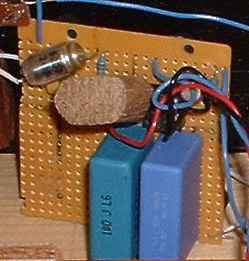
The OPA627 buffer, the filter cap (6n8) and resistor (695R) are on the top left corner.
|
|
Once the buffers were tested, and the PSU modified as regards plugs and leads, it was a simple to job to connect the buffers into the temporary set up. I then measured the DC offset on the speaker terminals and found that it had not changed; so I reconnected the speakers, put a CD in the drawer and sat down to listen.
|
| Site menu
Page menu
|
|
|
Actually I have to confess that when I pressed play, only one channel came to life. I found a loose wire on the input of one buffer, re soldered it and then had stereo once again.
|
|
Well, this is one change to the IGC which you notice straight away. The sound is if anything, more solid. Yes, the sound stage grows larger and (surprisingly) the control that the amp has on the sound is even more tight. I have always marvelled at the way the IGC keeps control of quite complex passages of music; in fact that is one of the areas where it is clearly superior to my much modified Arcam A60's. But with the buffer, you feel that nothing could phase this amp. It gives the impression of having much more power, bass is more pronounced and it just makes it harder to sit there listening to a loud track of rock music knowing that you have just two (comparatively) small capacitors and a 120VA transformer keeping it going!
|
|
I also noticed that I could bring the volume quite loud without there being any trace of edginess. The top frequencies have certainly been tamed by the LPF and that may account for the feeling of increased bass too.
|
|
I don't think that I can pinpoint any negatives with this modification. If I had to be extremely fussy, there may be a very slight loss of transparency but I would have to switch back and forth between the basic GC and buffered version a few times to be sure of that. I have only had a short audition with the buffers and I prefer to reserve final judgment until I have had longer to assess things properly but my first impressions are that the buffer will stay; the only question then will be whether to try a valve buffer!
|
| Site menu
Page menu
|
|
|
I have lived with the buffered IGC for a week now and am no less thrilled with the sound that it produces! A friend who heard this GC without the buffer/LPF has also been back to listen to it with the buffer and he also noticed the obvious improvement! I am convinced enough to embark of the valve buffer!
|
|
One thing that I have noticed with the buffer/LPF, is that the amps run warmer. I am not sure why but apparently Pedja has noticed this too. The increase in heat is nothing to worry about but if I get time, I may try and investigate this phenomenon further!
|
| Site menu
Page menu
|
|
|
First I would like to say that the OPA buffered IGC now runs at a very low temperature. Why it was hotter to begin with I don't know but it soon cooled down. This is a phenomenon that one of two other builders have experienced with new chip amps although there seems no rational explanation for it.
|
|
Well, it's a year since I first built the buffered IGC and in the mean time I have built the VBIGC and had plenty of time to listen to and compare the two amplifiers. I won't go into a comparison here as I want to stick to the subject of SS buffers, and report on my most recent experiments.
|
SS - Solid State ie using transistors or opamps as opposed to valves.
|
|
|
|
I recently built some new opamp buffers to try with the IGC. Apart from making a few improvements to the buffer circuit, I also included opamp sockets to allow me to easily swap between different opamps and compare their sound. Other changes were:
- Some gain to allow me to use opamps like the NE5534 which is not stable at unity gain.
- A small circuit on the output of the opamp to allow me to bias the output into class A.
- Moving the voltage regulators as close as possible to the opamp voltage pins.
|
Class A - Class A amplifiers amplify over the whole of the input cycle. Class B amplifiers only amplify half of the input wave cycle. As such they create a large amount of distortion, but their efficiency is greatly improved. In simple English this means that Class A amplification is 'smoother' than Class B but at the cost of less efficiency. However, in the case of small signals, which is what we are dealing with in the buffers, the wasted energy is not a huge problem.
|
|
The new buffer (note the trimmmers to adjust the rail voltages).
And the circuit (excluding the LPF).
|
|
A few notes on building the circuit:
- Try and get the regulators as close as possible to the voltage pins of the opamp.
- I used 15 uF Oscon SG's for the main decoupling caps. They have very low impredance so I used the 0.22R resistors between the regulator output and the Oscons to maintain stability. If you use other capacitors you probably won't need the 0.22R resistors.
- I use double regulation in my PSU for this circuit. The first stage of regulation reduces the voltage to 21 volts which is the input voltage to this circuit. You may use different voltages but remember that the LM317/LM337 will require input voltages at least 3 volts great than your desired output voltage.
- Input and output DC blocking caps (2.2 uF input and 4.7 uF output) can be ommitted if you are sure that there is no DC.
- The circuit that biases the output into class A uses two transistors and two resistors (and is connected to the opamp output via a 1K resistor. I chose this circuit as it is one of the easiest to implement and doesn't require you to measure JFets etc. I used half of a 14 pin DIL socket so that I can easily insert or remove the 1K resistor in order to try the opamps with and without the class A circuit in operation. Please note that the class A circuit is designed to work with +/-15 volt rails!
|
|
Testing the new buffers
For my test, I decided to connect the new buffers into the same IGC that I have been using with the original OPA627 buffer. The tests were done in my 'second' system using the same two CD's of well-recorded test tracks and I gave each opamp at least one day 'in the socket'. Candidates were NE5534 (two actually, one made by TI, the other by Philips), OPA604, OPA627AP and OPA627BP.
|
|
At this stage I could emulate a hi-fi reviewer and wax lyrically about the various attributes of each opamp. Instead I will just say which I preferred and why.
|
|
Surprisingly the opamp that I liked best was the Philips NE5534! This was clearly the most musical of the opamps that I listened to although those who like hi-fi rather than music may find the more up-front sound of the OPA amps more to their liking. However, I found that when things 'got busy' as in the case of a full orchestra, the sound of the OPA's went a bit hard and not nice to listen to over long periods.
|
|
I tried all opamps with and without class A biasing. The 5534's benefited from class A whereas the OPA627's seemed to be slightly better without it! I also tried adjusting the rail voltages as I used a trimpot instead of the 2K4 on the regulator adjustment. However, this seemed not to make any difference, at least none that I could hear.
|
|
So it looks like the Philips NE5534's will be used in the new buffers except for the fact that I also took my discrete (transistor) buffers out of the drawer together with their discrete regulator circuits and tried them in the IGC. This is harder to call and I will need to do some more comparisons with the NE5534's. The two sound similar in tone, perhaps the discrete circuit being slightly 'sweeter' with the 5534's having a little more 'slam'. I will also be trying the opamp buffers with the discrete regulators and will report back here with my findings!
|
|
Update 25th August 2004
Continued listening with the Philips 5534 buffers confirmed how more more I preferred them to the other opamps. I altered the circuit to unity gain with resistors values of 100K, 100K and 50K (two 100K in parallel) and added a 22 pF cap to keep the 5534 stable. The idea was to reduce the DC offset to zero and try the buffer without an output cap. However, the offset was still high enough for me not to want to try it. There is a circuit to reduce the offset on the 5534 to zero but I don't currently have the parts, and to be honest would like to avoid the added complexity.
|
|
Then somebody told me about the NJM2114 (JRC2114) dual opamps. He had heard some in a CD player but when he used two of them as 'single' opamps he was really impressed.
|
|
Another good friend, Carlos Machado, had a pair of JRC2114's and sent them to me from Portugal. While they were coming, I built a pair of new buffer circuits to use the dual opamps. The results are indeed very good. At first, the 2214 buffers didn't seem as open as the 5534's. This may be due to quite a prominent treble on the latter. But listening closer, I could tell that the 2114's resolve detail slightly better than the 5534's. To be honest, I am still not sure which I like the best but it's very pleasent trying to find out!
|
| Site menu
Page menu
|
|
|
Now, just to make matters even more complicated, I received a design for a discrete transistor buffer from Andrew Rothwell of Rothwell Audio Products. It is actually based on a circuit by the late Les Sage who wrote in the Audio Conversions DIY hi-fi magazine. The design as you can see below, is very simple and operates in class A. Transistors recommended by Mr Sage were BFQ232's (NPN) but I have used BC547's and ZTX653's and the sound is very good. In fact, I think that this may resolve my opamp dilema!
Simple class A discrete buffer circuit. (Note you must use a DC blocking cap on the input as well as the output of this circuit!)
|
|
Update September 2005
Quite a few people have built the three-transistor buffer and reported good results. Dave Brooks has gone further and experimented with some different transistors. Here are his findings:
The transistors I've tried are the 2SC1825, BC637 and BC547. They are
all in the TO-92 package and with a little bit of leg-bending fit into
my transistor sockets so are easily swapped.
They all sound very good but subtly different, which I have to admit
surprised me - although it probably shouldn't have.
The BC547 is the brightest of the 3 and whilst not unpleasant, may not
be to some people's tastes. I also found this transistor a little bass
light.
The 2SC1825 is probably the smoothest or warmest sounding, with the most
pronounced bass but at a cost to treble performance. These seemed to be
much more suited to classical or piano music where their natural sound
worked very well. Not as well suited to rock music.
The BC637 was (to my ears) the best compromise - good bass, not too
bright with excellent treble and plenty of low-level detail.
To summarise, the buffer circuit is a brilliant piece of work. I know I
have described how I think it sounded with the various transistors, but
it always sounded excellent. The best advice I could give anyone
building this circuit is to fit the transistor sockets and try a few
different transistors. When you are working with Hi-Fi of this sort of
quality the "best" sound is so much a matter of personal taste that the
only way to find out what works best for you, in your room, with your
system is to try it out.
And Dave reported back a little later:
I've now built a buffer with the BFQ Transistors... Anyway, regardless of any theory it sounds absolutely fantastic and better than the other transitors I have tried. I don't know how they'll
sound in your system, but in mine there is definitely some magic happening.
William Ward has also been kind enough to share his experiences with this buffer:
Buffer Results:-
- BFQ232's:- I found the buffer using only BFQ232's did not suit my system at all. The sound was full, rich and satisfyingly "dark" to be sure, but the music sounded unbearably slow, and there was a distinct loss of high frequency information. After trying to alter the (hardwired) circuit and running into problems with my experimental board, I subsequently rebuilt it on stripboard, with transistor sockets so that I could experiment at will. So far, my findings have been as follows:-
- 3 x BC550:- Bright, not very good.
- 3 x BC637:- A very solid, clear, well-balanced sound, but tended to be a bit plodding - a bit "wooden" and uninvolving.
- 3 x BC639:- Emphasised extremes, particularly treble. Lively, involving sound, but a bit tiring due to hissy and overblown treble and lack of midrange.
- 3 x BC549:- Didn't work properly. Created low hiss/hum.
Combinations:-
- Some combinations worked fine, and some did not work at all in my circuit. I might have been able to get them going had I known what to fiddle with, but it was much easier to just try different transistors.
- Some combinations that worked well for me:
- Q1,Q2 - BFQ232, Q3 BC549. Pretty good.
- Q1 BFQ232, Q2 BC639, Q3 BC549 - better - left it in for a couple of days.
- Q1,Q2 BC639, Q3 BFQ232 - outstanding! Has the liveliness of the BC639's but the BFQ232 elevates it to another level of depth, clarity and resolution. I hadn't even thought to try this combination before, as I thought that Q3 must be nothing other than a constant current source/sink and couldn't have any influence on the sound. Well, whatever it is doing, it definitely DOES influence the sound.
I was running this from an unregulated power supply with only 3 pairs of caps for filtering, though the diodes in the rectifier are snubbed. I have now adapted two chokes I took out of computer power supplies and fitted them into the P/S. This brought a slight but audible improvement. I than added a snubber in the buffer's case - bigger improvement. My system is sounding far and away the best it ever has at the moment
William Ward wrote to me recently (Oct. 2006). He has also been playing around with the simple three-transistor buffer and says:
If you can get your hands on some ZTX 1053a's, then do yourself a favour and give them a try in this circuit. KSP2222a are also very good (and very cheap too!- but make sure you get the right ones - 75v; 0.6a; 300Mhz; 100+ hfe))(btw - have you tried driving one of these buffers with another one? The improvement is quite dramatic - possibly as much as adding the first one. Coupling capacitors can be omitted, though not the output caps.
If you have tried different transistors with the three-transistor buffer, let us know what you have tried, and how it sounded.
|
|
16th October 2005. Well I have just changed a BC547 in Q3 for a BFQ232 and agree with Will that it improves the bass, top end and clarity! Q1 is still BC547 and Q2 ZTX653. The reason for getting the buffer out again is to use it with the class-T amps that do seem to benefit from an active stage! Many thanks to Will for his work on this circuit.
|
|
Carlos Martinez (all my friends are called Carlos) has written to me suggesting that I should try my single opamp buffers without the 0.22R resistors after the regulators. The reason I use them is that somebody suggested that the extremely low impedance of the Oscon SG capacitors may cause a stability problem. However, the resistors also add impedance to the output of the regulators so I will try without them. This is a never-ending exercise but fortunately, I have the luxury of being able to do it in my second system as and when I feel like it. I wouldn't bother if I had to change my main system around so often!
|
|
Discrete buffer with Jfets.
I also built the discrete Jfet buffer designed by Pedja Rogic. I built the circuit exactly as specified by Pedja except that I used an IRF530 instead of the IRF510. This makes no difference to the operation of the circuit.
|
|
Because I didn't have a 47n cap for the LPF, I used a 39n with a 100R resistor instead of the 75R.
|
|
Pedja Rogic Jfet discrete buffer circuit.
The stripboard layout for the Jfet discrete buffer circuit.
|
|
This buffer circuit is not difficult to construct although not as straight forward as the discrete BJT version above. The main issue is to orientate the fets correctly, that's one reason I have included the actual layout above.
|
|
Also note that the 270R resistor is shown as a 'starting point' only! It is a good idea to use a 500R or 1K multiturn trimmer in this position to start off with. Set it to 270R and then apply the power to the circuit. Carefully measure the voltage across the trimmer and then use a calculator to divide the voltage by the resistance (in ohms). This will give you the current drawn and you want to aim for round about 6mA (0.006A). If it needs adjusting, alter the resistance (probably up), measure it, and then measure the voltage again. Do this until it is close to 6 mA. You will need to do this for both channels! You can leave the trimmers in place or replace them with suitable value resistors.
|
|
UPDATE August 2008
If you like the idea of having a Pedja Rogic GC, ie with the discrete buffer, but don't feel that your skills extend to building them, there is good news! Pedja is now selling kits/modules for improved versions of these items. For more information click here.
|
|
So, how do these buffers sound? I find the discrete buffers sound better than the various opamp buffers that I have tried. I wouldn't even attempt to decide which of the two discrete buffers is the best. It's much more a case of listening to them both and picking a personal favourite. As both use the same PSU, it's not a big, or costly job to build them both and decide for yourself!
|
| Site menu
Page menu
|
|
|
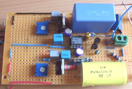
As has been discussed, when a buffer is powered up, it produces a noise for a second or two (longer in the case of a valve buffer while the heaters come to full power) and that noise will appear through your speakers if your amplifier is powered up at the same time (or before) your buffer section. In the case of a valve pre, it could damage a connected solid state power amp even if that is not powered up at the time! Of course, the answer is to power up your preamplifier before the power amplifier but what if your wife/partner or somebody else keeps forgetting to do that? It won't do the speakers any good. So we need a solution and here it is.
|
|
I'm not sure who to credit for this original idea so I can only say that it is not mine! But it is a clever idea as it does not involve adding anything extra (like a switch or relay) in the signal path. If you use the same power supply that you use for the buffers, then all you need are seven components (including the PCB) to deal with both channels.
|
|
Parts list:
- Trimmer 500K (single turn will do here) set between 100-470K.
- NE555 timer.
- Capacitor. I used 47 uF.
- DPCO Relay. Voltage to suit PSU. A 12 v type will do for a 15 v supply.
- Protection diodes - 1N4001 or similar.
- Stripboard.
|
|
As you can see, it is a simple circuit and once you have figured out which relay to use and which way round it goes, it is a simple job to build it on a piece of stripboard.
|
|
This is the relay that I used. Farnell order code 1174987. Digikey part number Z117-ND is another option.
|
|
The (signal) connections to and from the relay are as follows:
- Signal from output of buffer to points SL (left channel) and SR (right channel).
- Signal out from SL and SR. Take this to the input of the amplifier or the output sockets if the buffers are in a separate enclosure.
- Ground connections from relay at GL (left channel) and GR (right channel) to signal ground star of power amplifier, or ground tab of output sockets if in separate enclosure.
Please note that the relay is wired so that the contacts are normally closed. This shorts the output of the buffers to ground. After the delay, the relay is activated, the contacts open, and the output is no longer shorted.
|
|
Using a 47 uF capacitor I find that I get a variable delay from around 3 to 27 seconds, depending how the trimmer is adjusted. This means that there is absolutely no noise if I turn on the buffers section while the power amplifier is powered up. And there is no noise when the buffers are powered down.
|
|
The only thing that you need to be careful of when adding this circuit to the output of your pre-amp, buffers, or active crossovers, is to make sure that when the output is shorted, it doesn't draw too much current through the circuit and overload any transistors or opamps. I have tried the circuit with the transistor buffers described on this page with no problem. For more information on this subject, I suggest that you read through this thread on the diyAudio forums. Thanks to all those who contributed to that thread.
|
| Site menu
Page menu
|
|
|