|
Decibel Dungeon
|
|
|
|
My VBIGC.
With a brace of Gainclones under my belt, I had established that not only is the inverted Gainclone a fine sounding amplifier but that adding a buffer significantly improves the sound. I had also been intrigued by Joe Rasmussen's valve-buffered Gainclone and having built a valve pre amp earlier in the year and liked (very much) the 'valve' sound, I resolved to build a valve-buffered GC (VBIGC) next. This project would have probably come a bit later except that I was spurred on by Peter Moore who had built a VBIGC and was raving about the sound. When Pete kindly offered to send me a few parts to get me going, the project was on.
|
| Site menu
Page menu
|
|
|
As usual there were some decisions to take before the final design took shape, never mind the actual construction.
|
|
The two previous Gainclones that I built used a separate PSU connected by two umbilical leads, one for each channel. With two more transformers needed for the valve supply, this would mean another seven wires requiring an umbilical lead and plugs/sockets. Apart from the cost, the space required for the extra sockets on the back of the amp also posed a problem for the small design that I was envisaging. In addition, the mains supply for the Velleman protection unit would require yet another connection and this was just one lead too many for my liking.
|
|
So, I chose to put the extra two transformers (for the valve buffers) in the amp housing but was then concerned about the vibration they may add to the chassis which could get picked up by the signal circuits.
|
|
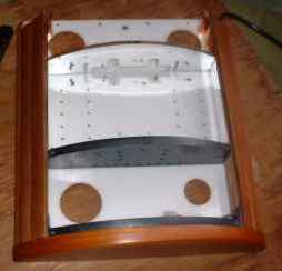
To minimise the contact of the transformers with the chassis I decided to mount them on their own stands which would protrude through the baseplate of the chassis. The design is shown in the picture below. The transformers are held just above the baseplate of the case.
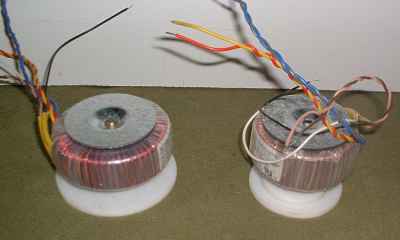
A polycarbonate disk and a shaped piece of wood make a simple but effective isolating mount for the transformers.
|
|
The next question was what to use for heat sinks. My experience with the OPA627 buffered IGC was that it ran a bit warmer than the un-buffered version. I was also out of the thick aluminium bar that I had used for the first two IGCs. Computer CPU cooler heat sinks seemed like a good idea but have a lot of thin fins which can pick up vibrations and transfer them to the chip. So I decided to mount the heat sinks inside the amp and by cutting holes in the base and lid of the housing, I would assist the cooling by causing a convection effect.
|
|
To further reduce any ringing effect from the heat sink fins, I ran a bead of hot-melt glue across each section as shown in this picture. The results were stunning, all the ringing disappeared and this should work well on exterior mounted heat sinks if you can live with the aesthetics.
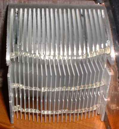
It actually doesn't look that bad!
|
|
Another issue was whether to use speaker protection. I am currently using a Velleman 4700 protection module with my original IGCs although there has been no problem in the couple of months now that they have been connected to my precious Goodmans 201's and I am now tempted to go without.
|
|
However, with a new amp, it is wise to be safe rather than sorry and I therefore chose to include a Velleman 4700 in the new amplifier. The Velleman 4700 has the added advantage of delaying the switch-on of the speakers to avoid the 'thump' that sometimes occurs when an amplifier is powered up. The delay is around 6 seconds, plenty long enough usually but in the case of a valve buffered amp, there will be a period while the heater filaments warm up and a nasty squeal can result while they do. To counter this, some people, like Peter Moore, use a delay circuit to switch on power to the amp section after the valves have warmed up.
|
|
I may go for this approach later but for now have modified the Velleman 4700 to have a 14 second delay (Peter Moore calculates a delay of around 12 seconds is sufficient for this circuit). If you want to do the same, it's quite simple, just replace capacitor C11 which is 220uF with a 470uF and Bob's your uncle.
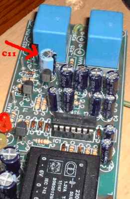
Just one capacitor and, hey presto, a delay of around 14 seconds.
An added advantage of including the Velleman module was that I could use it's +/- 6 volt supply rails to power the two blue LED's which I wanted to place under the valves. This makes no difference to the performance but should look good, especially as I have used a mirrored finish for the interior 'walls'. Yes, I have previously stated my preference to avoid LED's but so many people report that they can't hear a problem with them and in this case, they are supplied by a separate transformer.
|
|
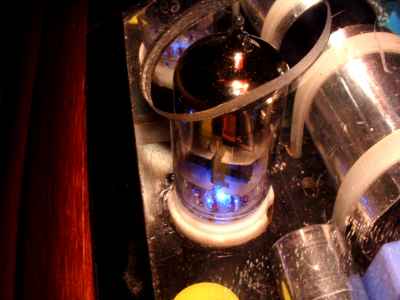
Yet another decision was whether to have the valve exposed or not. There's a real temptation when building valve gear to expose the valves and watch them glowing on a cold winter's evening. Well, for me there is anyway! The down side to this is once again the possibility of picking up airborne vibration and valves are particularly microphonic. Some people put metal cans over the valves or use other devices to reduce the vibrations. I didn't like the idea of the cans from an aesthetical point of view so after a lot of thinking, I came up with the idea of a transparent lid which would show off the valve but keep it relatively safe from vibrations outside of the case.
|
|
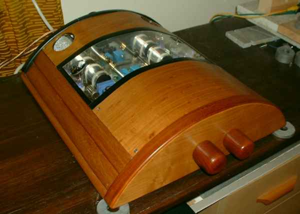
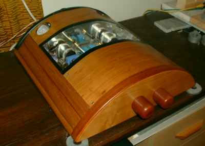
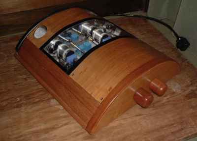
The big decision based on aesthetics was what type/shape of case would I build. I wanted to do something different but didn't have money to throw at this project and if you are not careful, the case can become the most expensive single component in a build like this! As usual, the rules were simple; build what I liked but only with what I had lying around the house give or take the odd nut and bolt. Well, I like curves and I like wood, so inspired by an airplane hanger (as somebody on a forum suggested) I came up with the following.
My original concept which was modified along the way.
|
|
The base is made from a piece of white polycarbonate (yes, I could have told you it was PTFE but I'm an honest sort of guy) originally found in a skip on a small industrial complex. The mahogany sides were painstakingly cut from a single piece of mahogany that I 'inherited' when I moved into my last house. The back panel and cross members are cut from good old MDF and the front plate is another piece of mahogany donated by a friendly woodworker and veneered with cherry wood veneer from the same source, as is the lid, which is a piece of perspex also found in a skip. The knobs are turned from a piece of mahogany by cutting them roughly to shape and then hand sanding them in an electric drill. (More details on that HERE.
Despite the curves, it is still basically only a 'box!
|
|
Coming to the actual hi-fi circuits, I am indebted to Peter Moore for providing me with a tried and tested design which he had built, based on an original idea by Joe Rasmussen.
|
|
This is a simple cathode follower design which many dismiss as lo-fi. However, as Peter M says, it's not the reputation that you listen to!
|
|
The power supply for the valve circuits. I used a single transformer for this PSU.
|
|
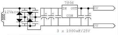
This is a very simple circuit to provide a DC supply for the heater filaments. I actually used a 220uF cap before the regulator and a 100uF after it (and left out the other smaller caps shown here). There may be better but this works and I wanted to keep things simple and get the amp built rather than spend months researching an alternative. That can be done later if necessary.
|
|
The actual amplifier circuit (shown above), based on the LM3875 chip, is the one Joe Rasmussen originally suggested on the diyAudio forum and differs from my original basic IGC as follows:
- The input capacitor is 4.7uF (47uF in the mono blocks)
- The input resistor is now 18K (10K in the mono blocks)
- The feedback resistor is now 1 meg (216K in the mono blocks)
- The resistor from non-inverting input to ground is 1meg (216K) and has a 0.1uF film cap in parallel with it.
- There are no 0.1uF bypass capacitors on the decoupling capacitors
- There is a 0R22 resistor on the output.
|
|
Click on this for a larger version of the wiring layout diagram (valve buffer circuit).
|
| Site menu
Page menu
|
|
|
Well, it's one thing to dream and draw things out on paper/in a graphics program, it's another to actually convert the dreams and drawings into something real. That's true when building a simple rectangular box, but with the curved shape that I wanted, it was a bloody nightmare. Mocking things up with pieces of cardboard helped a little but it wasn't until I had built each part of the amp, that I could actually see where it came in relation to the other parts. For instance, it was almost impossible to cut the apertures for the valves until the valve modules were built and put in place. As you can see, there is very little room for error, and with most of my materials being 'one-offs', any mistakes could potentially see the end of the project as it was originally planned.
|
|
Cutting the side panels from a single piece of mahogany about 3 inches by one inch meant that there was absolutely no room for error. Using a hand-held circular saw to cut angled cross sections is not for the faint-hearted but I'm reasonably pleased with the outcome. Although the case looks complex, if you could buy some extrusions to use for the side panels, the rest (apart from the lid) is quite straight forward.
|
|
Yes, that lid. Well, I found the piece of perspex in a skip and it had a few scratches but was otherwise OK. Having built the base, side panels and cross members, I carefully measured the size of the lid and cut the perspex using a bandsaw. The edges were finished with a sharp craft-knife blade and then the apertures for the valves were cut using a hole saw and a small grinding wheel attached to an electric drill. Now came the tricky part.
 - to accurately measure the size of the lid prior to bending it into shape, use a long strip of paper or tape. Run this over the curved shape of a cross member and mark on it where it touches the sides of the case. Remove it, lay it out flat and then measure between to two marks that you made. - to accurately measure the size of the lid prior to bending it into shape, use a long strip of paper or tape. Run this over the curved shape of a cross member and mark on it where it touches the sides of the case. Remove it, lay it out flat and then measure between to two marks that you made.
|
|
I located the perspex so that it made contact with one side panel and held it down with a straight piece of timber. With my free hand, I played a hot air gun over the perspex and let gravity put it down onto the bulkheads. I actually only needed to press down the last few inches and hold it in position while it cooled. It's not a perfect curve but given my resources, I am not going to loose any sleep over it!
- Get somebody to help you with this job or grow a second pair of hands!
|
|
I then veneered the front and rear sections of the lid with cherry wood veneer to match the front panel. This effectively hides the less attractive parts of the amp, ie the transformers and the input wiring. The veneer is stuck on with contact adhesive.
|
|
The black trim around the aperture is plastic strip bought from a hardware store (well not everything is available in skips) and is stuck on with superglue.
|
|
Originally, I built the back panel as one piece but later decided to cut it into three parts. This meant that the whole input section, input sockets, selector switch and volume control, could be removed in one piece. Also, each amplifier section would be a complete module, ie the power-in sockets and loudspeaker sockets would be attached to the amplifier and heat sink making it easy to remove the whole section for any future modifications. It's attention to details like this that can make any upgrading feasible rather than a pain in the neck!
The three sections that make up the back plate.
|
|
The mains supply for the valve section is facilitated via a fixed umbilical which runs through a groove in one of the side panels.
|
|
Keeping with the modular theme, I built the valve PSU's and valve circuit onto one piece of board (for each channel) and as these were going to be visible through the perspex lid, I tried to make them as neat as possible. I also skinned some of the capacitors, dressed the large 4.7 uF's in foil tape and added the (almost obligatory) blue LED's under the valves. The power for the LED's is taken from the Velleman module via a 1.2K resistor. Also note the large apertures at the ear of the lid allowing air to convect over the specially shaped heat sinks. Krell owners, you'll just have to do without this sort of quality ;-)
|
|
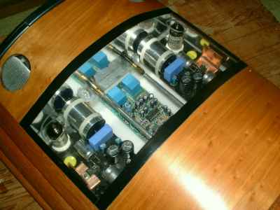
The mid section of the amp revealing the valve modules and Velleman speaker protection module. Exposing your work like this certainly makes you take more care!
|
|
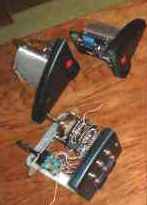
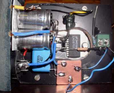
The valve modules, consisting of their power supply sections: rectifiers, caps, and regulators, and the valve circuits were built onto stout pieces of fibreglass board. If you look closely, you can see that they are not exactly mirror images of each other as that idea came about after I started building them. One problem that arose from adopting a mirror-image approach was that I wired one of the 6 volt regulators the wrong way round, ie I swapped the input and output pins around. I mention this in case anybody else does the same thing and makes the mistake of thinking that the regulator is at fault (like I did)!
|
|
The valve circuits are actually very simple and can be built onto the pins of the valve holders. Pete had kindly sent me a couple of 4.7uF polypropylene caps which are too big to fit under the boards with the other components so I dressed them up in some foil tape to increase the 'eye-candy' count! As Pete had also supplied them, I went with the bog-standard rectifier bridges although that is one area for possible improvement later.
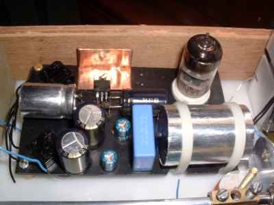
A top view of one of the valve modules. The modules are hard wired with the components stuck to the board using a little hot-melt glue.
The heat sinks are home-made from scraps of copper tube. In my case the regulators drop the voltage from about 12 volts to 6. If you use a higher supply, you will need larger heat sinks!
|
WARNING - if you skin caps like this, do make sure that they are not in contact with any other conductive material. If you do not understand this, please do not skin your caps.
|
|
Again, the amplifiers were built as stand-alone modules. This means that they can be removed by desoldering just three wires. Having decided to use one of the attenuators that I had already (rather than build another), I found that the larger size encroached on the amplifier and meant that I had to be careful to leave enough room to solder the connections when everything was in place.
|
|
As with my previous IGC, I screwed pieces of the black fibreglass board to the heat sinks with a hole cut in them to allow the chip to be placed directly on the heat sink. This means that the other components are separated from the heat sink and kept cooler.
As usual ,the components are stuck in position using hot melt glue to reduce any strain on the P2P solder connections. The little green component holder is to facilitate trying different filter capacitors.
|
WARNING - if you skin caps like this, do make sure that they are not in contact with any other conductive material. If you do not understand this, please do not skin your caps.
|
|
As with my previous Gainclones, I have made up my own speaker terminals. For details of how this is done, please see HERE.
|
P2P - point to point, a method of construction used instead of using a PCB to solder the components on to.
|
|
The input module consists of the centre section of the original back plate with two brackets holding a piece of aluminium angle section which holds the volume control and selector switch in position. Again, it quite easy to remove this whole section should the need arise.
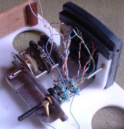
The input module.
The stepped attenuator is built on a 32 position Blore Edwards switch mechanism although I only use about 20 of the positions. It is a shunt design, keeping just two resistors in the signal path for any volume setting. The resistors used in the most often used volume settings are Welwyn RC55 types.
|
|
The selector switch is constructed from a rotary switch mechanism and 2 pole, 6-way non-shorting wafers so that both the signal and return can be switched in or out. I am not sure how much better one of these selector switches is better than a simple rotary switch but with the latter costing about 10% of the DIY kind, I may well try the 'simple' route next time!
|
|
Building everything into the case was fairly straight forward although making the connections to and from the amp circuits was a bit fiddly due to the lack of space. It was really a question of deciding which end of a wire should be soldered first so as to leave the other end more easily accessible when each module was in place. I suppose that fitting so much into a relatively small space will result in a slightly more fiddly job and that's one of the prices to pay for this type of design. Perhaps next time I'll just use a large rectangular box; then again, I can't change the habit of a lifetime.
|
|
The other bit
The last job was to build a housing for the two power supplies for the LM3875 circuits. This housing, a simple rectangular box (yes I can do them too) also houses a fused outlet for the (mains) supply to the valve transformers and Velleman protection module.
|
| Site menu
Page menu
|
|
|
Having completed the modules, I did some testing but was a little confused by the results. This was not due to something being wrong, but rather me not understanding that certain parts of the circuit affect the circuit as a whole and consequently I got some rather strange readings from my meter. Fortunately, a chat to some of the 'expert's got me going again but I will record my experiences here in order that it may help any others that follow in my footsteps.
|
|
The first bit of confusion was when I measured the DC offset on the amplifier modules. I was expecting close to 0mV but got 1.36 volts on both channels. It transpired that the LPF capacitor needs to be in position on the input of the LM3875 and when I put it in, I found that I had indeed got under 1mV of offset on each channel.
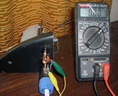
Measuring DC offset on the amplifier section. Note the 10 ohm resistor across the output.
|
|
A similar thing happened when measuring offset on the output of the valve modules but once again, when everything was connected up the readings were 'normal'.
|
|
Of course, apart from checking the DC levels on the output, there are other necessary checks to complete before powering up. In the case of the valve modules, don't power up with the valve in place. First check the voltage at the output of the regulator and make sure that it is 6.3 volts plus or minus 5%. While you are checking, make sure that you have the correct rail voltages, ie +/-35 volts (give or take a couple depending on your mains supply) if you have used a transformer with 25 AC secondary windings as recommended for this design.
|
|
When you have checked the supply voltages, you could try connecting an old speaker to the output of the valve modules, and with a source connected, you may just hear some faint sounds coming from the speaker.
|
| Site menu
Page menu
|
|
|
Well, it looked OK but that's nothing really in hi-fi if it doesn't sound good too!
The finished job - not bad for a morning's work!
Fortunately, straight from the first track I played through it, the VBIGC sounded very good. The speakers that I am using it with have a 95dB sensitivity and there is a slight hum with the ear adjacent to the speaker. But it is not noticeable from the listening position and once the music starts playing, it is forgotten instantly.
|
|
It's still too early to make a full comparison with the OPA627 buffered IGC but initially, it sounds lighter and airier. In fairness, the OPA627 version does not have the stepped attenuator and I have not checked that the LPF values produce the same results. For now though, after a long build, I am just happy to sit down and listen to it. So watch this space for further reports.
|
|
Update 16th November 2003
Shame on me, I still have not tried the LPF with the higher values of capacitor. My excuse is that I have been enjoying the sound coming form this amplifier so much, it is a Herculean effort to even think about changing it!
|
|
Just before I started using the VBIGC in my main system, I pulled the drivers from my speakers and have been using them on crude open baffles. The result is a fantastic room-filling sound with the speakers now so 'open' that the VBIGC is shown off at it's best. I would say that the amp continued to improve for about two weeks. Now, virtually anything I play brings immense enjoyment and I am focussing on improving the baffles both performance-wise and aesthetically.
|
|
I heard an interesting story today. A group of mainly valve-head DIYer's got together for a meet and one of them took his VBIGC along. Apparently even the die-hard valve-lovers were astonished by the sounds produced; one even calling it the most exciting thing that he has heard in audio for a long time!
TO BE CONTINUED.....
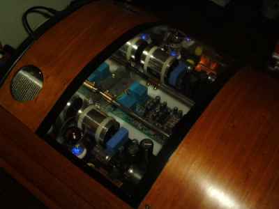
All lit up!
|
|
Here is another valve-buffered IGC link:
Tubes and Gainclones (Joe Rasmussen) .
|
| Site menu
Page menu
|
|
|