|
Decibel Dungeon
|
|
|
|
The preamp consists of a (separate) power supply, an input stage (the phono sockets and a selector switch), the volume control (a stepped attenuator) and an output stage which also doubles as the active crossover. If you're completely new to DIY hi-fi, you may be surprised at how few components it takes to make what is really two items in the hi-fi chain; the preamp and active crossovers. Combining the two saves on components and cost.
|
|
A plan of the power supply for the preamp is shown below.
|
|
|
|
The components that you will need to build it are: (codes shown are Farnell Electronics unless stated as Maplins). I believe that both these suppliers will ship worldwide but if you want to purchase locally, you should have enough details of the components to do so.
|
|
IMPORTANT
If you do not fit the components recommended below, make sure that the alternatives are safely rated. All capacitors must be rated at a minimum of 35 volts DC or above. The resistors between the transformer and rectifier must be rated at 5 watts or above. The other resistors must be rated at .125 watts or above.
|
|
Mains lead (and plug)
Use a length of flexible mains cable or make your own by plaiting together three lengths of insulated wire and enclosing them in some heatshrink tubing.
A - Fuse holder and fuse
Use an open type fuse holder with a cover (Maplins codes KU30H and VJ57M) and an anti-surge fuse rated at 1 amp (Maplins code GL91Y).
|
ANTI-SURGE FUSE - when electrical equipment is switched on, there is a temporary inrush of current (especially true when using toroidal transformers and large value capacitors). Although it only lasts very briefly, this current is higher than the level of current drawn during operation and can blow a standard fuse. The anti-surge fuse is designed to withstand this initial surge of current but will blow if there is a sustained rise in the current level caused by a fault.
|
|
B - Mains switch (DPST)
Depending on the type of case you use and your skills/tools, it may be easier to fit a switch requiring a circular aperture (140-621) rather than rectangular (157-788).
|
DPST - stands for Double Pole Single Throw. With a double pole switch, both live and neutral conductors are switched for extra safety.
|
|
C - Mains transformer - 50VA 18-0-18 (step down)
I prefer toroidal type transformers, others prefer laminated and someone I know who has a lot of experience upgrading hi-fi swears by C-core types. For this project I recommend the Antrim brand toroidal transformer supplied by Maplins, code number DH59P. Antrim transformers are one of the better quality brands of toroidal transformers. Update April 2009 - Antrim Transformers are now sold by Trans-Tronic.
|
|
D - Resistors
The rectifier transforms AC to DC. A silicon rectifier is a semi-conductor, only letting current go through it when the output voltage is more than 0,5 Volt below the input. At that very moment it switches "ON". Inside a semiconductor there is a capacitance as well. This capacitor, together with the inductance of the wiring, causes a very sharp peak voltage to occur. This peak is too fast to be dampened by the connected (electrolytic) capacitors.
|
|
The solution is simple, put a resistor between the transformer and the rectifier. The value is not absolutely critical but I suggest for a preamp supply, a value of 10 ohms and rated at 5 watts (987-580)
|
A resistor rated at 1 watt would be high enough for this preamp but I couldn't find a suitable example in the Farnell catalogue, so I have specified the 5 watt.
|
|
E - Rectifier diodes (4 off)
Four rectifier diodes form the bridge rectifier which converts the electrical supply from alternating current to direct current. Note, that at the same time the rectifying stage changes the voltage by a factor of 1.414. I am currently using ultra-fast soft recovery diodes (367-357) which perform better than the standard equivalents.
|
BRIDGE RECTIFIER - 2 full-wave rectifiers connected together so that, both a positive & a negative voltage source is available using only 1 transformer secondary winding.
|
|
F - Smoothing capacitors (2 off)
The smoothing (or reservoir) capacitors store the electrical power (when there is a lower demand by the equipment) and release it at times when there is a large demand. A good compromise between performance and cost is to use the types made by BHC Aerovox. 4700 microfarads (536-192) is sufficient for this preamp supply.
|
MICROFARAD - which is abbreviated as ufd, is the unit of measurement used for capacitors. It can be divided into picafarads (pf) (1/1000,000ufd) or nanofarads (nf) (1/1000ufd).
|
|
G-K - Bypass capacitors (2 off each)
The large value smoothing capacitors should be bypassed with smaller values. I have used 4.7ufd polypropylenes, part number JY82D from Maplins which are in turn bypassed by 1ufd (286-916), 0.1ufd (286-886) and 0.01ufd (106-780) polypropylenes.
|
POLYPROPYLENE - a type of dielectric (insulating material) used in capacitors. Usually considered better than polyester and polycarbonate. Polystyrene is also considered to be good.
0.1ufd=100nf.
0.01ufd=10nf or 10,000 pf.
|
|
LM317 - Voltage Regulator (1 off for positive rail)
LM337 - Voltage regulator (1 off for negative rail)
|
RAIL - the name given to the conductors carrying a voltage, eg positive, negative or 0 (zero) volt.
|
|
As their name suggests, these devices regulate the voltage supply. Start off with the standard LM317 (412-132) and LM337 type (412-223). There are more exotic and costly regulators but I have not yet tried them.
 Make sure that you connect the regulators correctly as their pin arrangement differs. Looking at the LM337 from the front, the pins are (from left to right) Adj, vIn and vOut. The LM317 viewed from the front also has the Adj pin to the left but followed by vOut and vIn.
|
|
N & P - Resistors to set regulator output
The LM317/337 regulators are adjustable types which need to have their output set using a voltage divider consisting of two resistors. The output of this power supply is to be + or- 18 volts so, starting with a UAR value of 220 ohms (513-866) we can calculate from the formula
Vout = 1.25*(UAR+LAR)/UAR
that the LAR value should be 3K (514-135).
|
VOLTAGE DIVIDER - a circuit, usually consisting of two resistors which splits the voltage into two. In the case of an attenuator, it enables part of the voltage to be shorted to ground thus 'controlling' the volume.
LAR - lower arm resistor (P).
UAR - upper arm resistor (N).
Vout - output voltage.
|
|
Q - capacitors (2 off)
These 100 nF capacitors are to filter off any unwanted AC components on the voltage rails by allowing them to pass to ground via the 0 volt rail.
|
|
Output socket (and matching plug)
This will provide the means of connecting the psu to the preamp. The items I use (149-325 & 149-322) are designated 'for audio' in the Farnell catalogue but are rated high enough for this job.
|
|
A PCB
You could make up a PCB from a sheet of copper clad board but I suggest glueing (hotmelt glue is ideal) the components to a suitable board (I use a 3mm thick piece of fibreglass) and then hardwiring them together.
|
PCB - Abbreviation for Printed Circuit Board. The board on which electronic components are mounted to build a circuit.
|
|
A suitable case
I'll leave this up to you but I prefer to build my own. Remember, if you use a metal casing, it must be earthed (point Q in the diagram).
|
|
Odds and ends
You will also need some insulated terminals (to connect wiring to the fuse-holder and mains switch), a terminal block, a cable gland and some method of securing the mains lead where it enters the casing. As these items will depend on your type of casing I cannot make specific recommendations.
|
|
The above design can be modified in many ways although it will work well enough as it is. Potential improvements may come from placing RC filters either before or after the regulators to remove ripple and other mains nasties. Diodes could be placed across the regulators to protect them from reverse voltages although I have used this design without them for three years without problems. I prefer to use a combined circuit-breaker/switch(248-472) in place of the fuse and mains switch. It costs a bit more but circuit-breakers are reputed to perform better than fuses in audio equipment.
|
| Site menu
Page menu
|
|
|
Construction details
Produce a rough sketch of the layout of the components in the case (or do a scale drawing if you prefer). Work out where each component will go, particularly the mains switch and the output socket. Aim to keep the internal wiring as neat as possible.
|
|
The fuse holder and transformer should be bolted to the base of the casing.
The mains switch and output socket are mounted in the sides of the casing.
ALL conductive parts carrying the mains voltage must be insulated. Put a cover on the fuse holder and use insulated terminals to connect wires to the fuse and mains switch.
You should not need a ventilated case as the regulators will not run hot for the voltages specified.
Do make sure that the mains lead cannot chafe where it enters the casing and that it is firmly secured. Always leave the earth wire longer than the live and neutral wires so that if the lead is pulled, it is the last of the three wires to break contact.
The colour coding in the diagram is for the Antrim transformer as specified. If you use another type or make of transformer, make sure you know which leads carry which voltage.
Make sure that the diodes and electrolytic (4700ufd) capacitors are inserted correctly as regards polarity. The diodes have a band at one end of their bodies indicating the cathode and should be inserted as shown in the diagram. The capacitors must also be inserted as shown. The smaller value capacitors are non-polarised and can be inserted in either orientation.
If you hardwire this project (recommended) use a larger wire for the 0 volt rail.
Mark on your PCB the positive and negative rails - it's easy to mix them up later when making external connections.
|
|
IMPORTANT
The construction of this power supply should be well within the capabilities of most people with some DIY skills. It hardly needs saying that everything must be connected properly as in the diagram. Make sure that the case is electrically connected to the earth wire of the mains lead and that there is nothing causing a short circuit. If you have not built electrical equipment previously, find a qualified electrician and have them check your psu BEFORE you connect it to the mains. When you have connected it and switched it on, you should be able to measure around + and -18 volts at the output socket using your multimeter (set to DC). The third pin should measure 0 volts. If this is the case, your psu is completed and ready for use.
|
|
Please note that the output of this psu is +/- 18 volts. The circuits in the preamp will use +/- 15 volts and this will be obtained by passing the supply through a second stage of regulation. (The LM317/337 voltage regulators require an input voltage of at least three volts more than the output voltage) If you want to build a psu to power a +/- 15 volt circuit directly, you could use a 12-0-12 transformer and change the value of the resistors in the voltage dividers to 240R (UAR) and 2K7 (LAR).
|
| Site menu
Page menu
|
|
|
There are three options for creating a case for the preamp:
- Buy a suitably sized case. This is the most expensive option and still requires modifying to accept the component parts of the preamp.
- Build a case. The case could be made from timber, plastic or metal. If you have access to metal forming tools and equipment, perhaps this is an option.
- The third option, in my opinion, is the most practical for a number of reasons. It is to get hold of a non-working piece of hi-fi such as a CD player or amplifier, gut it and use the case. It should not be too difficult to find a suitable specimen which should be about 430 mm wide by about 250 mm deep. The height is not too important but avoid the very slim cases.
Whichever option you go for, you will need to modify the case as follows:
- The rear panel should have an aperture cut in it to accommodate the panel containing the phono sockets for input and output signals.
- A front panel should be fabricated from MDF, metal or plastic. This can be glued or screwed to the front of the casing. (For this reason, avoid casings with a sculptured front panel)
- The various sections of the preamp, the input selector switch, attenuator, crossover circuit and power supply board will need mounting. This is best achieved by bolting them to the base of the case using a stand-off. Check out one of the electronics component suppliers mentioned above for different types of stand-off.
Without knowing which option you take for your casing, I can't really give any further advice but it isn't too difficult to make something which looks as good as the hi-fi you can go out and buy.
|
|
You will need to plan out how everything will be located in the preamp. It's much easier to do this with paper and pencil first, than to spend hours fixing bits in and then finding that you don't have room for the last component! Below, is the plan (not to scale) of my preamp which works well, with everything located logically and internal wiring runs kept to a minimum.
The volume control and input selector switch are built onto a sub-chassis constructed from a flat piece of aluminium with aluminium angle (30mm x 20mm) pieces forming mounting plates for the switches and bushes which support the shaft extensions. The sub-chassis can then be mounted in the case at a height to suit the vertical positioning of the knobs on the front panel.
|
|
I mount both the voltage regulator and crossover circuit boards on suitable sub-chassis before bolting them into the case. There are many methods of fixing the circuits boards, as you will see if you look in the fastenings section of one of the major electronic components suppliers.
|
| Site menu
Page menu
|
|
|
The input section consists of:
- The input sockets. These can be phono (147-012/149-269) or XLR type and should be mounted on a non-conductive panel at the rear of the case. If you prefer to, you could mount the sockets directly onto the metal casework but in that case, you must use the insulated type of socket. Work out exactly where each socket will go, bearing in mind that internal wiring should be kept as short as possible. Mark out and carefully drill the holes in the material you have chosen for this purpose. With a little extra care, it is possible to get all the sockets evenly spaced in two straight lines.
- The input selector switch. This is constructed from a switch mechanism 146-046) and two wafers (146-057). I have specified a twelve position switch although there are only six inputs. I like to ground every other position on the switch to eliminate crosstalk between sources. Remember to get both wafers the same way round and have the 'out' tags facing the volume control.
Please note that I originally specified a Farnell part number of 146-017 for the switch mechanism. Since then I have used that mechanism in my latest preamp and found it extremely difficult to set the stops accurately. For that reason I would now strongly recommend the metal mechanism 146-016 as the better alternative.
- The volume control, in this case a stepped attenuator.
|
|
There are three types of stepped attenuator.
- In the first sort the total resistance is the result of the signal passing through an increasing number of resistors. At lower volume levels, this means that the signal will pass through many resistors and for that reason, I have dismissed the design.
- In the second design, the signal only ever passes through a maximum of three resistors. I used this design to build my first attenuator but it uses a lot of resistors, two switch mechanisms and ten wafers, making it rather costly.
- The third design, uses a minimum of resistors and the signal only ever passes through two. The disadvantage is that the total impedance changes at each volume setting. However, in practice, this seems to have no noticeable effect on sound quality so this is the design I favour.
Resistor formation in shunt attenuator (12 'steps' shown).
To build the attenuator you will need a suitable 24 position rotary switch mechanism. Fifty resistors are required and you can choose which type you will go for. The options are:
- Plain carbon resistors. Not recommended as they come with only a 5% tolerance and unless you spend a lot of time accurately measuring them, you will finish up with some degree of imbalance between the two channels.
- Metal film resistors. These come in 1% tolerance so are quite acceptable. The main advantage is that they are cheap.
- Welwyn RC55. These are my personal favourites based on sound quality, tight tolerance and a reasonable price. There are two types, the RC55 and the cheaper RC55Y.
- Surface mount resistors. A friend on mine prefers these as their construction offers a smoother signal path than resistors with leadout wires. Price wise, they are on a par with the Welwyns and another advantage is their compact size.
- If you want to go mad, there are a number of very expensive bulk-foil resistors from several manufacturers. Personally, I think that the law of diminishing returns comes in here and I can't see myself ever using them for this application.
|
|
An alternative to the expensive rotary switches used for stepped attnuators is to make your own from parts that you buy, ie switch mechanisms and wafers. These tend to be sold in two sizes, 25.4mm and 32mm. The larger sizes cost a little more but are probably easier to build onto.
|
|
The problem with building attenuators this way is that you are limited to a maximum of 12 switch positions which can mean having rather course steps if you want to provide attenuation over a wide range.
|
|
For an attenuator, you will require one switch mechanism and two wafers although using two dummy wafers as well will enable you to make a neater job!
 - You could make your own dummy wafrers from scraps of copper-coated PCB material or hard plastic. - You could make your own dummy wafrers from scraps of copper-coated PCB material or hard plastic.
Some spacers are also useful.
|
|
When building a switch, work out where the resistors are going before you start soldering, make sure that you get both wafers orientated the same way and with their wipers in the same position.
|
|
For this project, I suggest that you use an attenuator with a 100K impedance and you can find a list of the resistors that you will require by clicking HERE. The page also includes details for building attenuators with (average) impedances of 22K and 93K.
|
|
Building the attenuator is relatively straightforward.
- If there is enough space on the attenuator mechanism, buy or make two 'dummy' wafers (copper-coated board will do or a hard plastic) to match the switch wafers that you are using. Mount the wafers with spacers and you can then attach the resistors to them for an extra neat attenuator.
Resistors soldered to a dummy wafer.
- Turn the switch anti-clockwise until you reach the stop. Note the position of the contact on the rotating part of the switch. We'll call this 'position one'.
- It makes things much easier if you have laid out all the resistors in order (and labelled them). If you have not bought 1% types (or better) measure them on your meter to get the best matches.
- Now trim one leadout wire of each resistor to about 6mm and solder the resistor to the appropriate contact (see the diagram below). When you have finished ( if you are not using a dummy wafer), make a circle of copper wire (a length retrieved from some old mains cable is fine). The best way to do this is to find a jar or other cylindrical container (the same diameter as the circle you want to create) and use it as a former for the wire circle. Solder each resistor to the wire 'circle' and a wire from the 'circle' to signal ground. (As you should be able to see, this part would be easier using a dummy wafer)
- Solder the series resistors to the contact on the wafer mechanism making sure that they can't short with any of the other resistors. (I use a bit of sleeving cut from some bell-wire). The lead-out wire from the attenuator is also insulated and then soldered to the same point.
- Finally, reassemble the switch and mount it.
You can test your attenuator by attaching one lead of a multimeter to the input side of the series resistor, and the other lead to the ground connection. As you turn the knob of the attenuator clockwise, you should be able to see the total resistance increasing step by step.
|
|
If you are new to electronics, this may seem a bit strange - increasing resistance but the sound level also increases! This is because the resistance to ground is increasing as the volume control is turned 'up', not the resistance between the 'in' and 'out' sections of the attenuator circuit. As the resistance to ground increases, it 'forces' more of the signal to flow to the 'out' connection and the sound level increases.
Note, only some of the resistors are shown for clarity.
If you want to buy a stepped attenuator kit at a really good price, take a look at this from Diyfidelity in Australia. They will ship anywhere at reasonable cost and this really does represent a good deal for an excellent attenuator. It's not mentioned on the site, but if you ask them, they do accept payment by Paypal, making the transaction much easier and faster!
|
|
When you have your attenuator and selector switch built, you can install them in your case and wire them up to the input sockets. You will find it easier to solder the wires to the contacts of the input switch BEFORE you install it.
|
| Site menu
Page menu
|
|
|
Before we get on to the actual crossovers, we'll take a look at the power supply. A supply of 18 volts DC is taken from the separate power supply unit and is then regulated a second time. There is no real theory behind this idea of a second regulation stage but I am happy that it works, judging by the sound coming out of my 'speakers! There are separate positive and negative regulators for both left and right channels.
|
|
Please note that the original diagram had the resistor values transposed but they are now corrected (6th March 2004).
|
|
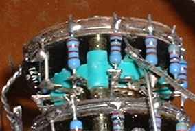
I suggest that the components for this regulation stage are glued onto a suitable piece of board using a hot glue gun after the necessary holes have been drilled to accept the leadouts. This is a comparatively simple circuit which lends itself to hardwiring, as illustrated by the red, black, violet and pale brown lines in the above diagram. The voltage regulators, LM317 and LM337 are only dropping the voltage by 3 volts and will not require any extra heat sinking. Be careful to get the polarity right with the capacitors on the input.
|
|
As regards the components, you can get better versions of the regulators (I think that they have the suffix letters 'AT') but these are more likely to be available from specialist component suppliers rather than the likes of Farnells, Maplins or RS. I suggest standard 1% metal film for the resistors. The 10 ufd capacitors something like Elna RSH's and a good polypropylene for the 100n's.
|
|
Remember to double check all your wiring and make sure that there are no short circuits. Although this section of the power supply only carries voltages of 18 volts, you should not be any less careful in putting it together. Even if you are unlikely to harm yourself, you want to ensure that some music comes from your 'speakers!
|
|
Now that we have a suitable power supply, we can build the active crossovers. Active crossovers come in an almost infinite variety, ranging from the simple (like the example here) to the ridiculously complex which can put so many components into the signal path that they probably negate the good that they do in replacing their passive alternatives.
|
|
I'm not stating that the following design is the last word in active crossover design, indeed many more qualified persons may find fault with the circuit. However, I have no hesitation in publishing the design because:
- It is simple and easy to understand for beginners.
- It is cheap (and comparatively easy) to build.
- It does sound very good. What it may lack in complexity is made up for by having a minimum number of components in the signal path.
But enough of the sales talk, let's have a look at the design. Rather than just putting up a circuit diagram, I have shown how to lay out the components.
|
|
|
|
Please note that the J500 CCS devices may be replaced by a 75K resistor and the J507's with 7K5 resistors.
|
|
The crossovers consist of two RC filters (one resistor and a capacitor) which are buffered between a simple emitter follower consisting of a single transistor. The values of the components shown in the diagram: 9K1 for the resistor and 6800 picofarads for the capacitor will give a crossover frequency of 2K6 Hz. Of course, you can change the crossover frequency by adjusting the value of either resistor or capacitor but 2K6 Hz is ideal for the system which is the Decibel Dungeon project. DC blocking capacitors are placed at the input and output. I have used current regulators to control the current flowing through the transistors although single resistors could also be used to do the same job.
|
|
As regards the components, I chose ZTX109C transistors for no particular reason other than they were readily available from Farnells at the time. I mounted them in transistor sockets (TO-18 Farnell Code# 177-128) with the intention of trying other types to see if they affected sound quality. Probably because I'm happy with the sound, I have not yet tried that experiment.
- apart from allowing you to easily change transistors over, using sockets removes the possibility of damaging the transistors when you install them by applying too much heat with the soldering iron. If you want to solder transistors in place, use a heat shunt to protect them from damage. These low cost tools are locking metal tweezers which can be clamped to a transistor leg and soak up the heat. (Maplins code FR10L)
|
|
I've used standard 1% metal resistors except for those forming the filters which are Welwyn RC55C's. They are actually 9K09 but are close enough not to make an audible difference. The filter capacitors are polypropylenes (BC 2222 460 46802). The DC blocking capacitors are all polypropylenes (see Farnell catalogue) except for the 10n's which are polystyrene.
|
|
Making a PCB is fairly straight forward as the tracks are relatively simple to follow. In the diagram the red tracks carry the positive voltage supply, the blacks the negative and the violet the zero volt rail. The pale brown tracks can be considered to carry the signal. All tracks are straight lines (unless you want to make them otherwise). I didn't draw the diagram to scale as you may well use components with different dimensions/lead pitches. When making a PCB, remember to leave room for the holes needed to mount it in the case.
|
|
And that's about it for the crossovers, they really are a good way to try active crossovers on a budget. If your preamp already has a suitable power supply (+/-15V), you could go active very cheaply although you would need an extra stereo amplifier of course. I've been really happy with the performance of this crossover design for a couple of years now. I'm not saying that I won't try something else eventually but the sound is certainly good enough to make that change a low priority in my upgrade plans.
|
| Site menu
Page menu
|
|
|
At this stage you should have a case containing the following 'sections' of your preamp:
- Input sockets
- Selector switch
- Volume control
- Regulator board
- Active crossovers
- Output sockets
If you have not already got one, get a three-core cable which will link the preamp to the power supply unit. This should enter the case through a suitable sized hole which has a grommet inserted in it to prevent the cable being chafed. The cable should be firmly clamped inside the preamp casing so that it cannot be pulled out. There are many types of clamp for this purpose, I usually use something I have scavenged from a defunct piece of equipment. Finally, connect the cable to a three-way terminal block which is bolted to the case adjacent to the regulator board.
|
|
Now you have to link them all together so that you get the signal through the preamp and on its way to the power amps. You also need to get power through the regulator stage and into the crossovers. And you want to do all this without landing up with a nasty hum coming from the loudspeakers. Here's how.
|
|
To keep things simple, I'll not give a description of every wire. Obviously the wiring is the same for both channels and the wires to and from each socket are identical in their arrangement.
|
|
The first question you may be asking is what wire should you use for this job. Should it be solid core or stranded, is copper good enough or is silver or silver-plated better? Well, I've tried both solid core and stranded, copper and silver-plated types. My opinion is that silver-plated wires give a slightly brighter sound if you want it and stranded wire gives a very slightly more even tonal balance while solid core types seem to emphasise the bass frequency. Having said that, it is a lot easier to use solid core and in my latest preamp I used standard 0.6mm solid core copper wire which was also very cheap. So it's really down to what you want to spend and how easy you want to make the job. Some people recommend shielded connections where they are more than a few millimetres long but I have not experienced any problems with unshielded wires.
|
|
|
|
Let's get the earth/zero volt/ground wiring done first. All these connections will go to a common point known as the 'Star Earth'. I suggest that you place this as close to the output of the volume control as you can (without making it too difficult to attach the wiring). I use a brass M6 bolt (see above) which is secured to a small piece of wood or plastic by a brass nut. This is then attached to be bottom of the casing so that the brass bolt does not come into contact with it. I solder ring terminals to all the earth wires so that they can be easily attached to, and removed from the earth 'post' The terminals are held securely in position by a second nut.
|
|
I suggest that whatever wire you have chosen that you stick to one colour for the earth wiring which is different from the rest of the wiring. Start off by taking a length of the earth wire and strip off enough of the insulation so that you can solder it to the ground tab on each of the input sockets. Make sure that it is long enough to reach the star earth point. Solder it in position and repeat for the other channel. Twist the two wires together and solder a ring terminal on the loose end. Slip this connection onto the star earth post.
|
|
Connect the GRND's of the attenuator, the zero volt of the regulator board and the zero volt wire of the connection cable in a similar fashion but do NOT connect the output sockets.
|
|
Next take a 100n capacitor and solder a 100 ohm (0.6 watt) resistor across the legs. Solder short lengths of wire to each leadout of the resistor and solder ring terminals to both ends. Insulate this item with some insulation tape then bolt one end to the case and slip the other over the star earth post. You can now use the second nut to secure all the connections onto the star earth post.
|
|
As with the earth wiring, use the same colour wire throughout for the signal wiring, with a different colour for each channel. At the risk of stating the obvious, make a connection between each input socket and the corresponding wafer on the selector switch. You can either use adjacent positions on the selector switch for the six inputs or you can use every other one. If you choose the latter, you will need to connect the vacant tags on the wafers with lengths of ground wire which is then run back to the star earth point. This method prevents any 'crosstalk'. You can sometimes here this if say you are listening to the CD player but have the tuner switched on and connected to an adjacent socket. When the CD player is silent between tracks you can hear the input from the tuner. It may be very feint but it's there. If we avoid connecting sources to adjacent inputs and ground the tags in between them, the unwanted signal is shunted to ground. Another advantage of this arrangement is to provide muting positions on the selector switch so if the telephone rings, you can mute the output without adjusting the volume control.
|
|
Connect the output tags of each selector switch to the inputs of the attenuator making sure that you don't mix up the left and right channels. The outputs of the attenuator are in turn connected to the inputs on the active crossover. The outputs of the crossover are connected to the output sockets, again don't mix up the channels and also remember which is the high output and which is the low one. I have got mine muddled on one or two occasions without mishap but it's best to be careful. Also note that you must connect the ground wires between the crossover and the output sockets (not to the star earth point).
|
|
Preamp wiring guide. Blue - Earth. Orange - signal. Black - negative voltage. Red - positive voltage.
|
|
Finally comes the wiring for the power supply. From the terminal block which is connected to the lead from the power supply, run wires for the positive and negative supply to the regulator board. Make sure you don't get them mixed up. Check all the wiring and if you are happy with it and you have had your power supply checked and approved, switch it on and measure the voltages on the output of the regulator board. If you get both plus and minus 15 volts, which you should, you can switch off and connect the outputs of the regulators to the supply rails of both crossover boards (assuming that you have made them separately). Switch on again and measure the voltage on the outputs of the crossover. There should be no more than a couple of millivolts there and if that is the case, the preamp is more or less finished.
|
|
To finish the preamp, make up a front panel and some knobs. I'll leave this up to your own taste but see the Building your own equipment section for some ideas and tips or click HERE to see a finished preamp built to the above specification.
|
| Site menu
Page menu
|
|
|