Hung up on DIY hi-fi?
Then welcome to

The safe way to building a Gainclone (chip amp) power supply for beginners.
![]()
![]()
Decibel Dungeon
Introduction.
After what seems like many years of building chip amps, and answering questions about them via Decibel Dungeon, and various forums, it is clear that for the newcomer to DIY hi-fi, the major obstacle in building a working chip amp (Gainclone), is understanding, and building the power supply. So I have decided to publish another page on DD that will deal with building a power supply in as much detail as I can add without making things too technical and confusing.Please also read and understand this very clearly. I cannot possibly cover the safety regulations for all countries. Even in this modern world where standardisation is an on-going process, the electrical standards for different countries can and do vary. The information provided in this guide, particularly that pertaining to safety, is based on my knowledge of the safety standards for my own country, ie the UK. If you don't live in the UK, I strongly advise you to check out all aspects of the guide with somebody knowledgeable in your own country, better still with the organisation that provides electricity to your home. It should also go without saying that I take no responsibility for any consequences arising from your use of any of the information in this article.
I would like to acknowledge the help I got in compiling this guide from Andrew Tymkewcz (AndrewT on the diyAudio forums) who kindly not only proof-read it all but made some corrections and suggestions for making it more comprehensive. Thank you Andrew.
What is a power supply?
That may sound like a stupid question and perhaps we should ask instead, what does a power supply (also known as a PSU for short) consist of. In order to safely build one we need to know what every part is, what it does, and where it goes. So here is a list, in some sort of order as regards how the electricity gets from your mains supply to the output of your chip amp power supply.
The mains wall socket.
Yes, of course you already have this part, hopefully properly installed by a qualified electrician. If I need to tell you where it is, or what it looks like, then please leave the class right now!
The mains lead from the mains wall socket to the chip amp.
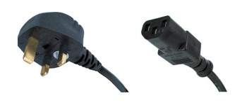
We will assume for the sake of this exercise that we will use a mains lead that plugs into our power supply rather than a captivated lead (one that is hard-wired to it). This is generally considered to be much more convenient than a captivated lead, more so if you later want to change the lead for a 'better' one. In the UK, we call this type of mains lead a 'kettle lead' because it is typically used to connect an electric kettle to the mains. Here is an example.
As you should be able to deduce, the lead is made up of three components:
The mains plug that goes into the mains wall socket.
This plug will of course match the type of mains sockets in your home. In the UK, the typical mains plug has three rectangular pins, and contains a fuse. Some countries still use a two pin plug with no fuse. If your mains supply still uses two pin plugs with no earth wire, you must consult an expert in your own country on how to make your power so that it is safely earthed.
The lead (or cable).
In the UK (and in many other countries in Europe, and the USA) this will have three conductors, one for the live supply, one for neutral, and one for the mains earth connection.
The IEC plug that connects to the equipment.
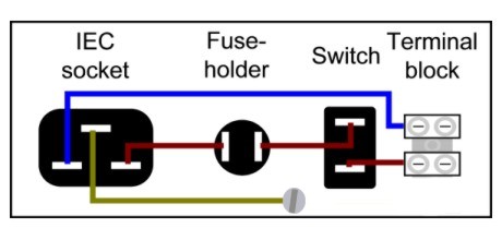
Please note carefully that although it is called a plug (more correctly a line plug) it actually doesn't have any exposed pins. The reason for this should be obvious but if you hadn't realised, I will tell you that if it did have exposed pins, they would be 'live' and therefore potentially lethal when the cable is plugged into the mains socket but not into your equipment. It is probably easiest to purchase one of these kettle leads ready-made but I mention the bit about the IEC connector in case you want to make your own mains lead. If you do, make sure that you use the IEC connector on the LEFT in the diagram below.
The input (panel) socket.
The IEC plugs and sockets are used just about anywhere in the world for connecting the mains supply to electrical equipment. If you look at the picture of an IEC panel socket below, you will see that it does have exposed pins. This is safe because when the mains lead is unplugged, there is obviously no power in the amp. So always remember, when using IEC plugs and sockets, the exposed pins are always on the part that is not connected to the mains.
It may be a good time to mention that if you take mains power out of your equipment, the reverse applies. So the IEC panel socket for MAINS OUT looks like this. Note that there are no exposed pins.
The fuse holder.
The fuse in the mains plug (if there is one where you live) is there to protect the mains lead. To protect the equipment, we have another fuse immediately after the IEC input socket. This could be housed in a fuse-holder that is mounted in a panel on the case, it could be mounted in a fuse-holder inside the case, or it could be held in a fuse-holder on a PCB. Which ever option that you choose you should remember that the fuse holder should be properly insulated so that you cannot accidentally touch a live part of it. For beginners, I would recommend a panel-mounted fuse-holder similar to the type shown below but note that the metal tabs will be at mains voltage so they must still be properly insulated!.
The fuse must match the fuse-holder so be warned there are several types and size of fuse. We will discuss what value fuse you should use later in this article.
The mains switch.
This will allow you turn on and off the mains power to your power supply. There are many types of mains switch but what we need to be concerned about is the electrical rating of the switch, rather than what type it is, or how it looks. Let's look at a typical mains rocker switch. Rocker refers to the action of the switch that 'rocks' or pivots across the middle of the switch housing. Other types are toggle, rotary (action) and push-button.

So what does it all mean?
First off, we need to know if the switch is rated correctly as regards current and voltage. You should know your mains voltage. It will either be around 115 volts, or 230 volts (but can vary by 10% or more up and down). If you don't know your local voltage supply find out from your electricity supplier. In our example we can see that the switch is rated for 250 volts AC. So that would be good enough for use with any domestic appliance in the world.
The other figure at the top is the current rating. The symbol for current is 'A' so if you are looking at a switch and see a figure with an 'A' suffix this is most probably the current rating. For a Gainclone power supply I would suggest using a minimum rating of 3 amps, so you can see that the switch above would be rated safely far in excess of what we need. But it is fine to have a higher rated switch than you need rather than having one which is rated too low. What happens if it is too low is that the contacts will get burned away by the electricity 'jumping between the switch contacts as you turn the power on and off (and causing sparks). Eventually the switch will fail.
The other specifications are not quite so important. Electrical life tells you how many times that you can expect to operate the switch before it fails electrically, ie it won't turn on or off the electrical supply to the equipment. Mechanical life is the same except it refers to when the switch will physically break (internally rather than externally).
The other figures don't really concern us as DIYers. They are quoted for the benefit of electrical engineers who have to consider other factors in designing their electrical projects.
The other specifications that you need to know for purchasing a suitable switch are the number of poles, and the 'throws'. 'Poles' just refers to the number of pairs of switch contacts. A single pole has a single pair of contacts and can therefore switch just one of the wires in the supply. A double pole switch has two pairs of contacts and can switch two wires. So you can either just switch the live wire in your supply, or switch both the live and neutral wires. In theory it is better to switch both, and as the cost of a double pole switch is not much more than a single pole type, it makes sense to do so. Of course, you may see a particular switch that you like the look of and it is only available as a single pole. Such is the life of the DIY hi-fier! 'Throws' refers to the number of positions that the switch can be set to. In our case we just want a switch that is either on or off so we want a single throw type.
Summing up, choose the type of switch that you want to use, select a single pole or double pole type (single throw), check that it is rated at 3 amps or more, and that the voltage rating exceeds your mains supply voltage. You can get illuminated switches if that is what you want but the wiring will be slightly more complex. A data sheet for the switch concerned should show you the necessary connections to make.
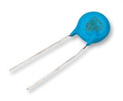
![]() - Place a small Class X1 rated capacitor (around 0.1 uF /275 volts is fine) across the switch contacts. This will help protect the contacts from arcing and also stop them from making a noise when the switch is operated. This is optional but recommended.
- Place a small Class X1 rated capacitor (around 0.1 uF /275 volts is fine) across the switch contacts. This will help protect the contacts from arcing and also stop them from making a noise when the switch is operated. This is optional but recommended.
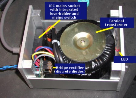
The mains transformer.
Now we start to get the parts of the power supply that cause the most confusion. The transformer must be able to supply the correct voltage, and 'enough' current for the circuit(s) that they will supply. To know how much voltage the transformer needs to supply, you need to know the rail voltage(s) that the amplifier (chip amp in this case) will run on. Then using a calculator, divide the rail voltage by 1.41.For example if the chip amp runs on 27 volt rails, 27 divided by 1.41 is approximately 19 volts. The closest that you are likely to find is a transformer with 18 or 20 volt secondaries so you would choose one of those. Alternatively you could have a transformer specially wound to provide the 19 volts but this will be much more expensive and really, a volt or two in this case doesn't make any difference.
One thing you need to be careful about, and that is how mains voltage variation can affect your secondary rail voltage. If a transformer is rated at 230 volt on the primaries, and your actual mains voltage is say 240 volts then your secondary rail voltage will go up accordingly. For instance, if you use a transformer with 25 volt secondaries, and expect to get 35 volt rails, you will actually get nearly 37 volts. If the mains voltage went up to 250 volts ( and I have measured mains voltages in my home at over 250 volts) you would get over 38 volts. This may, or may not go over the limit for your chip, but it is something that you need to be aware of when calculating the voltage rating of the components that you use in your power supply and chip amp.
Another transformer characteristic can affect the actual voltage going through your circuit. That is transformer regulation. Smaller transformers have higher regulation than larger ones which means that when they are not loaded by playing music, they can increase the voltage on the rails. If you stick to the suggested VA ratings suggested in this article, that shouldn't be too much of a problem. But it helps explain why you should over-rate items like capacitors by a factor of 1.25. And that 1.25 should be factored in after you assume that you could get the highest mains voltage, rather than the nominal voltage. I'll confirm this when I talk about the reservoir capacitors.
To make things a bit easier as regards selecting a transformer with the correct voltage, here is a table. Look up the chip that you are using, then your speaker's impedance, and then look in the third column to read off the secondary voltage suggested. Please note that these are 'safe' recommendations, and not the full range of voltages that may be used, ie it is a guide for those that can't understand the chip data sheets. The last column shows the DC voltage that you will get after the bridge rectifier. This figure may vary by a volt or two depending on your actual mains voltage supply that can and does drift up and down during the day. But even if it does drift by the maximum amount permitted, your supply will still be in the safe range suggested by the chip manufacturer.
| Chip | Speaker impedance | Sec voltage | DC after bridge |
|---|---|---|---|
| LM1875/6 | 4 ohms | 18 VAC | 25 volts |
| LM1875/6 | 6 ohms | 18-22 VAC | 25-28 volts |
| LM1875/6 | 8 ohms | 20-22 VAC | 28-31 volts |
| Somebody wrote to me suggesting that the 1875/6 chip will last longer with the following settings: | |||
| LM1875/6 | 4 ohms | 12 VAC | 15-17 volts |
| LM1875/6 | 6 ohms | 14-18 VAC | 19-27 volts |
| LM1875/6 | 8 ohms | 18 VAC | 25-27 volts |
| ------------------------------------------------------------------ | |||
| LM3875/6 | 4 ohms | 18 VAC | 25-28 volts |
| LM3875/6 | 6 ohms | 18-22 VAC | 25-28 volts |
| LM3875/6 | 8 ohms | 20-25 VAC | 28-35 volts |
| LM3886 | 4 ohms | 18 VAC | 25 volts |
| LM3886 | 6 ohms | 18-22 VAC | 25-28 volts |
| LM3886 | 8 ohms | 20-25 VAC | 28-35 volts |
| LM4870 | 4 ohms | 18 VAC | 25 volts |
| LM4870 | 6 ohms | 18-22 VAC | 25-28 volts |
| LM4870 | 8 ohms | 20-25 VAC | 28-35 volts |
| OPA541 | 4 ohms | 20-25 VAC | 25 volts |
| OPA541 | 6 ohms | 18 VAC | 25-28 volts |
| OPA541 | 8 ohms | 18 VAC | 28-35 volts |
| OPA549 | 4 ohms | 20-25 VAC | 25 volts |
| OPA549 | 6 ohms | 18 VAC | 25-28volts |
| OPA549 | 8 ohms | 18 VAC | 28-35 volts |
Calculating the current requirement is a bit trickier. There is a formula but you need to know some other technical information such as how much power you want your chip amp to provide. As this is a 'dummies' guide, I am going to pass on that one and give you some general guidelines instead. For each channel of a chip amp, I suggest a minimum of 80 VA. So for a stereo chip amp with one power supply I would suggest the transformer is rated at 160 VA. You can go much higher of course,with extra cost and physical size being the limiting factors. But I would not recommend going above 300VA per channel because you would be unlikely to get any further sonic advantage, and you would be into the area where you would need to consider a soft-start system that adds a whole lot more complexity to the supply. Even if you use a 300VA for each channel, I would suggest switching them on and off with separate switches.
The other thing that confuses people about transformers is the different types. Very briefly, a transformer is a transformer. That is, it accepts an electrical supply at a certain voltage and current, and converts it to a different voltage and current. It doesn't make any difference what size the transformer is, or how it is connected (some have metal tags, and some have flying leads). So don't get too hung up on which type to use but typically, a toroidal type is used for most chip amps.
Three different types of transformer: toroidal, R-Core, and laminated core (or EI).
IMPORTANT - if you use a transformer that has a metal chassis (like the two shown above, centre and right) you must ground the chassis , either by using a nut, bolt, and star washer to connect it to the earthed chassis of the amplifier, or by using a short length of wire from the transformer chassis to the equipment chassis ( ie when mounting the transformer on isolating feet, eg rubber washers). Also make certain that no part of the metal bolt/nut/washer touches the top of a metal case or you risk causing a short circuit that could result in the transformer catching fire.
Let's get to grips with what is what on a mains transformer. A transformer is basically two or more coils of copper wire that are wound around a metal core such that one coil runs parallel to the other. What happens is that when the electricity flows in one coil it induces electricity to flow in the coil running parallel to it. If the length and diameter of the wire making up the two coils is the same, the same amount or electricity comes out of the transformer as goes in (less a little that is lost on the way). But if the coils are different, it causes the voltage and current coming out of the transformer to be different values to that going in. That's why we use them, because we don't want 115 volts or 230 volts going to our chip amp circuit, we want something much lower, typically 18-40 volts. And because the voltage is lower, the current is higher, something else that we want.
One of the coils is called the primary winding. This is the coil that connects to the mains supply. Get that into your head now, the primary coil (or winding) is the one that connects to the mains supply (after the mains switch(. The other coil (or winding) is called the secondary, and that as you have already worked out (I hope) connects to the rest of the power supply that we are building. Of course, what makes things a bit more complicated is that there is often more than just one pair of windings.
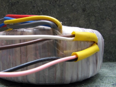
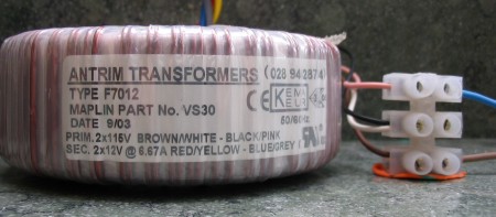
Some mains transformers are supplied with just two connectors or wires on the primary side. This makes things very straight forward as we have only two wires coming in from the mains input socket. You can connect the two wires to the two wires or connectors of the transformer and the polarity doesn't matter because we are still using AC (alternating current) . But in order to make a transformer that can safely be connected to both types of mains supply, ie 115 and 230 volts, some manufacturers put two coils on the primary side that can be wired in series or in parallel. Here is a picture of a toroidal transformer with twin primary windings (the brown, white, black, and pink wires).
The diagram below shows how to wire the above transformer for either 115 volts or 230 volts operation.
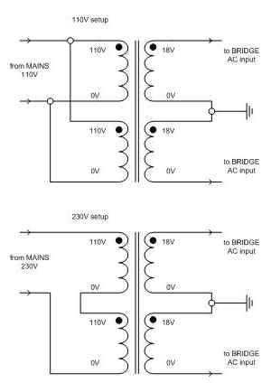
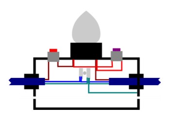
Wiring diagram showing a transformer with 18-0-18 secondaries connected for 110 volt or 230 volt mains supply (for a single bridge rectifier).
But how do we know which wire to connect where? Fortunately, the answer should be on the side of the transformer, if not, then on the manufacturers web site. This is what you should see if you look on the transformer.
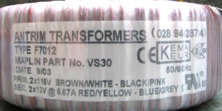
Let's start with wiring the transformer for use on a 230 volts mains supply. In this case, we need to wire the primary coils in series and we do that by joining two of the wires together. And the two that we join together, are the two in the middle of line marked PRIM for primary. So in this case, the black and white wires are joined together and then the other two are connected to the incoming mains power supply. It doesn't matter which way round you connect the two wires.
For connection to a 115 volt supply, the primary coils are connected in parallel. This means that the four wires are divided into two pairs. In this case we take the first colour or each pair (ie brown and black) and join them together to make one mains connection and then the other two wires (ie white and pink) are joined to make the other connection.
Remember to join the two wires securely and safely. That means insulating them. A terminal block is a good option.
A transformer wired up for a 230 volt mains supply.
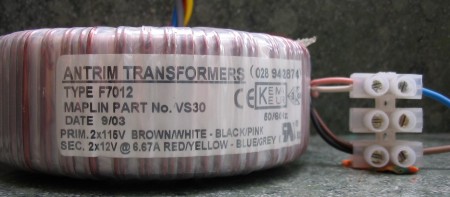
A transformer wired up for a 115 volt mains supply.
And that's it, not very difficult but easy to get confused about so take you time and re-read this section until you understand it. If you don't have access to the information on the label, or the manufacturer's web site, then you will have to try asking on a forum if you know the make of your transformer. Don't write to me, I don't have the specifications for all the transformers out there so I won't be able to help you.
Having sorted out the primary connections for the transformer, we now look at the secondary connections. These cause equal confusion for DIY newbies. We will ignore transformers with just a single secondary winding because a typical chip amp power supply needs both positive and negative rails, hence the transformer needs to have two (or twin) secondary windings.
If you look at the first picture of the example transformer, you should also be able to see the leads for the secondary connections. They are the red, yellow, blue and grey wires. If you wonder how I know that, have another look at the picture of the label! So where do these four wires go to?
This depends on whether we will be using a single bridge rectifier (the next item in the chain) or a pair of them. A single bridge rectifier has only two AC connections (AC is what is coming out from the transformer). But we have four wires! So what we do is join two of those wires together and those will form the ground rail (don't worry about that just yet). As with the primary side connections, we join together the two wires in the middle of the line, but this time the line marked SEC, ie the yellow and blue wires. Then the other two wires go to the two connectors on the bridge rectifier marked with a ~ (that denotes AC which is what comes out of the transformer). Again, it does make any difference which wire goes to which side of the bridge rectifier.
If we are to use two rectifier bridges, then we simply take one pair of wires for each bridge rectifier. In this case the label tells us that one pair is red/yellow and the other pair is blue/grey.
Before we move on from secondary connections, we will look at another transformer option that you may have. That is called a centre-tapped transformer. It is the same as the twin secondary transformer but the two secondary coils have been joined together and only three wires emerge from the transformer. In this case you can only use a single bridge rectifier, so if your design calls for two, then you will have to buy a new transformer. If you do have a centre-tapped transformer and you use a single bridge rectifier, then you connect two of the wires to the bridge, and the remaining wire is your ground rail. A centre-tapped transformer usually has two of the secondary wires in one colour and the third in another. It is the odd coloured wire that is used for the ground rail and the two wires the same colour are connected to the bridge rectifier.
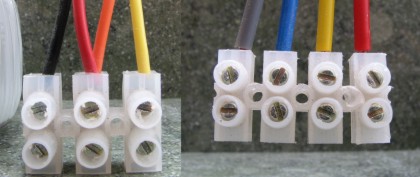
Secondary wires from (different) transformers with twin secondaries showing how they are configured to supply a single bridge rectifier (left) or a pair of bridge rectifiers (right).
If you are using a different type of transformer to a toroidal, and cannot relate to the above advice on making the correct connections, please ask on a DIY forum rather than writing to me. Whatever you do, if you don't know the correct connections, don't try to guess them. And finally, may I remind you, the colours of the wires quoted above are for the Antrim transformer shown in the picture. The colour codes are NOT universal, and the wires on YOUR transformer may be coloured coded differently.
The bridge rectifier.
There are several types of bridge rectifier, eg half-wave, full-wave, etc. We will be looking at full-wave bridge rectifiers which is what just about everybody uses with a chip amp PSU. The job of the bridge rectifier is to take the power from the transformer and convert it from alternating current (AC) to direct current (DC). If you want to understand why we need DC and not AC think of the AC as a variable item. If we add a variable signal to our audio signal that is also variable, we get an unpredictable result. What we want is a predictable result, ie our audio signal that looks exactly the same but is larger (so it can drive the speakers). So DC is what we want, and the bridge rectifier supplies it for us.To further complicate matters, there are not only many types of bridge rectifier. So you can not only buy them ready built (below left), but also make them from discrete diodes (below right).
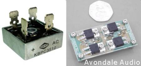
Note on the bridge rectifier on the left, the tags are marked + and AC. The AC connections are more usually marked with the ~ symbol.
Choosing a bridge rectifier can be daunting given the number of choices. For a typical chip amp, I suggest something that is rated at 3 amps or above. And of course, it must be rated for the voltage supplied by the transformer. As always, if you are not sure, go higher rather than lower with the ratings and you will be safe.
If you are more ambitious, and want to build your own bridge rectifier from discrete diodes, the first question that needs to be answered is what diodes to use. You could use something cheap and cheerful like the 1N5400. But most Gaincloners opt for something a bit better, in particular the MUR860. Most of the kit suppliers also supply the MUR860 in their kits.
Some people like to add snubber capacitors across each leg of the bridge rectifier (or each discrete diode). This in theory at least reduces noise from the switching actions of the bridge so I always suggest trying them if you want to. A small polyester capacitor will serve well for snubbing and won't cost much.
The reservoir capacitors, (also called smoothing capacitors).
Basically, these capacitors store some power from the power supply so that it is always able to supply enough power to the amplifier circuit. It sort of keeps some power in reserve, hence the term reservoir capacitor. These can be almost any value from a few micro farads, to 10,000 uF, or even more. What is important is that they are rated at a high enough voltage for the circuit that they will be used in. In fact we also want a bit of a safety margin here so a good rule is to take the rail voltage and multiply it by 1.25 and then go for the next highest rating. And remember to cater for the highest mains voltage. If you mains supply is said to be 230 volts it can be as high as 10% more, ie 254 volts. So a transformer with 25 volt secondaries would actually be putting out 25 x 1.1 = 26 volts (AC). Multiply that by 1.41 and you get nearly 39 volts. It is that 39 volts that should be multiplied by 1.25 so any components should be rated at 48 volts or more. In that example you would use capacitors rated at 50 volts. For example if we have an 18 volt transformer giving us around 27 volt rails (after the bridge rectifier) then 27 x 1.25 is 33.75 so you should go for capacitors rated at 35 volts or higher. If all this maths is too much for you, here is a table to tell you what capacitor ratings to us with which transformer secondary voltage. Just read off your secondary voltage in the leftmost column and the suggested component rating in the rightmost column.| Traffo sec volts | Poss. highest output | x 1.41 (to DC) | 1.25 safety margin | Suggested rating |
|---|---|---|---|---|
| 12 | 13.2 | 18.6 | 23.3 | 25 |
| 15 | 16.5 | 23.3 | 29.1 | 35 |
| 18 | 19.8 | 27.9 | 34.9 | 35 |
| 20 | 22 | 31 | 38.8 | 50 |
| 22 | 24.2 | 34.1 | 42.7 | 50 |
| 24 | 26.4 | 37.2 | 46.5 | 50 |
| 25 | 27.5 | 38.8 | 48.5 | 50 |
| 30 | 33 | 46.5 | 58.2 | 63 |
Capacitor brand and type is another area where you have almost too much of a choice. You can read the forums to see what others are using, or just choose something from your local supplier to suit your budget. And just to make it more complicated, there are different types of capacitor depending on how you intend to mount them. If you are using stripboard for your bridge rectifier and reservoir capacitors, then I suggest you use the PCB type of a capacitor. If your capacitors are going to stand alone in the case, the stud mounting variety may be better. Snap-in, and solder tag types usually required a mounting bracket
Secondary fuses for the power rails.
These are optional but recommended as a safety measure, particularly when you have a new build and are testing your power supply. They are probably best located in fuse-holders mounted on the same board as the bridge rectifier and reservoir capacitors, unless the chip amp you are supplying already has fuses in it. For secondary fuses we use the quick-blow type as we want them to blow as soon as we get a problem.
Make sure that you get the right sized fuses for your fuse holders. Unlike the fuse on the primary side of the transformer, these fuses will only carry low voltages so it is not essential to insulate them. If you are using this guide to build a power supply for something that requires higher voltage rails, then I would recommend insulating the secondary fuse/fuse-holder if the voltage rails are greater than +/-35 volts.
The safety ground (earth) connector.
There is another 'component' that is not actually part of the power supply, but is very important as regards safety. This is the connection of the power supply to ground (or safety earth) such that in the event of a fault, the current leakage will be shunted to the earth connection and not remain in the case, or anything conductive that is part of the equipment such as a metal knob, or connector. This subject is discussed much more comprehensively here on Rod Elliott's excellent ESP site and I strongly urge you to read it all and try to understand it!This is the method of connecting the safety earth as shown in the ESP article.
And this is the particular part of the circuit that we are talking about now. To build it you will need:
- a 35 amp bridge rectifier
- a 5 watt 10 ohm resistor or power thermistor
- a 100 nF capacitor
- a piece of wire
- 4 crimp terminals for fit the bridge rectifier terminals
- 1 crimp on ring terminal
- suitable nut and star washer to connect the earth wire to you metal case where your mains safety earth connection is.
And...
And that's it, apart of course from a suitable case to put all this in unless it is going in the same case as the chip amp. Next we will see how to put all these bits together to give you a working power supply.
Building the power supply.
For this part of the guide we will make some assumptions. First that you will use a kettle lead that is already assembled. Second that you will use a separate IEC inlet socket, fuse, and switch. You could of course use a single unit with all three items included and that does make life much easier. You only need the one hole in your case panel, and you have fewer connections to make. Third, that this power supply will supply a basic stereo chip amp with a single power supply shared between both channels. And finally we will assume that the equipment is earthed. And please take note, this guide pertains to building a power supply for use on the UK mains system so the wiring colour coding, and mains voltages involved may be different if you live outside of the UK. If that is all understood then let's begin.
The first job is to install the IEC socket, fuse-holder, and switch, in the case. I will let you decide if you want them all on the rear panel, or with the switch on the front panel for easier access. Either way, you need to cut some holes in the panel(s) This is not a general DIY article so I will let you decide how best to cut the holes. I use an electric drill, and a round file that cuts through aluminium or plastic quite easily. Remember that you could also use an 'all-in-one' IEC panel socket with a built in fuse and switch. That would mean only one hole to cut, and fewer connections to make inside the case.
Now take your transformer, choose a suitable place to mount it in your case, and secure it using the large dished plates, nut and bolt that was hopefully supplied with it. Some people like to add a compliant material (rubber etc) underneath the transformer such that it offers some physical isolation between the transformer and the case. The transformer will vibrate when power is applied to it and it is considered beneficial to minimise the amount of vibration transferred to the case, and therefore to the electronics in the case. This may also result in the (mechanical) transformer hum being less audible. In any case, you should place something compliant under the transformer to ensure that there is no chance of chaffing the insulation around the windings. That's why most toroidal transformers are supplied with those large rubber circular pieces of rubber.
![]() - When thinking about where to locate all the parts of the power supply, neatness and appearance is one thing, but don't forget that you have to connect them all up, so make sure that you don't put items too close together to get your fingers, or a tool, into position where required.
- When thinking about where to locate all the parts of the power supply, neatness and appearance is one thing, but don't forget that you have to connect them all up, so make sure that you don't put items too close together to get your fingers, or a tool, into position where required.
Next we are going to make some connections. There are two wires carrying the power, and an earth wire. Let's start with the live wire. First off make sure that you know which terminal on the back of the IEC socket is live. If you are lucky, it will be marked, often with a small embossed 'L'. If not then you could plug in the kettle lead (but not with it plugged into the mains socket) and check the continuity from the live pin on the mains plug using your multimeter (assuming that you know which pin on the mains plug is the live one of course. (if you don't, open up the mains plug and the check continuity from the fuse to the IEC socket)
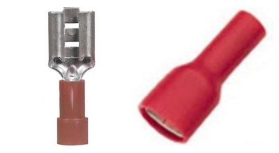
How will it be the wire be connected to the IEC socket? You could solder the wire directly to the terminal. You would then need to insulate it properly, perhaps with some heat shrink tubing. I would suggest a better alternative is to use an insulated receptacle like the one shown (below right). The uninsulated type is also shown to give you an idea of what they look like. These types of terminal are also called 'Fastons'.
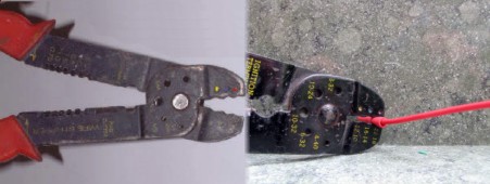
These terminals are quite easy to attach to a length of wire using a special tool. If you were doing thousands of these connections, it would pay you to buy a good crimping tool. But for a few crimps, a much cheaper tool can be found in most electrical shops, and looks like the one below.
The crimp terminals are colour-coded for different sizes of wire. When crimping the terminals, use the same colour on the crimping jaws as the terminal colour. You should also match the gauge of your wire to the terminals. Usually a red connector will suffice for a chip amp power supply, but to see which wires fit in which terminals, please refer to this data sheet.
If the fuse holder also has a tag to accept a crimp terminal use one on the other end of the wire. Try and use the same colour coding for the wiring on the primary side of the transformer, as is used in the mains cable. In Europe this would be brown for the live wire, blue for the neutral wire, and a green/yellow stripe for the earth wire. (In America it is black for live, white for neutral and green for earth). So cut a length of brown wire to reach from the inlet socket to the fuse-holder. Don't make it too tight. Crimp on the terminals and attach the wire. Now make up a similar wire with insulated terminals, to go from the fuse-holder to the mains switch. And finally, another length of brown wire from the mains switch to a two-way terminal block. This terminal block should also be bolted to the case. Make sure that the wires going to and from the mains switch are connected to the same pair of switch contacts. You can test if they are, using your meter providing that you don't have the mains lead attached to your PSU .
Now do the same for the neutral (blue) wire but this time you miss out the fuse-holder. If you wish, you can fuse the neutral line too, and in some situations you must. One such situation is when feeding your power supply from a balanced supply but if you run your equipment direct from the mains socket, it will not be a balanced supply.
Now run the earth (green/yellow) wire to a connection on the case/chassis. This is one of the most important connections in your chip amp so get it right. Here is how Rod Elliott suggests it is done in his article on earthing hi-fi equipment.

Note that the mains earth connection is made using a crimp on (Faston) ring terminal (NOT soldered), and that is held permanently in position by the first nut. Any other connections are made without removing that nut and secured with a second nut. That way, you can't accidentally forget to replace the mains earth wire.
Your wiring should look this the diagram below which shows the IEC socket, fuse-holder, and mains switch viewed from the rear.
The wiring you have done will provide a switched and fused mains supply at the terminal block ready for connecting the transformer to.
Assuming your transformer is safely mounted in the case, connect the primary wires of the transformer to the three-way terminal block. If there are only two primary wires from the transformer, then they simply go into the terminal block opposite the live and neutral wires. If there are four primary wires coming from the transformer see here for details how to wire them up correctly.
On the secondary side of the transformer, take the connecting wires to another terminal block, again bolted to the case. If you have three wires, use a three-way terminal block, if you have four wires, use a four-way.
If you want to check the secondary voltage of the transformer at this stage, remember to connect up the bulb-tester as described here. The bulb-tester will prevent disaster if you have somehow got the transformer wiring wrong.
Next up is the bridge rectifier. Remember, for this example we are going to build one from discrete diodes. I will use MUR 860 diodes but the same applies to any other rectifier diode. We have a few options here:
- Hard wire the diodes together. Although this is relatively easy to do, and the MUR860's won't need a heat sink, I would still not recommend this approach for beginners.
- Use a piece of strip board and solder the four diodes to that. This actually works quite well and is what I use in most of my builds.
- Make up a PCB to take the four diodes. This will look best but unless you can find a ready-made item, it will involve the time and expense of getting one made up.
So let's go with the strip board. Strip board is readily available everywhere and not too expensive. If you don't know what it is, or what it looks like, have a look at this.
Start by cutting a piece of strip board to the correct size. For the MUR860 diodes, I suggest having a piece of strip board roughly 21 holes wide by 15 strips long. This will allow enough from for the diodes, the connections, and some holes to mount it in the case.
Now work out where each diode will go. Try and keep things symmetrical. The circuit diagram for a bridge rectifier looks something like this.
Circuit diagram of full discrete rectifier bridge.
'A' and 'K' refer to the anode and cathode connections of the diodes. Have a look at the picture below and see if you can work out which leg of the MUR860 is the cathode, and which is the anode.
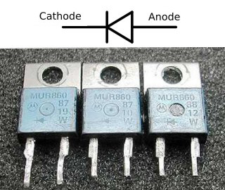
Yes, it's a touch confusing because the symbol for the diode is reversed on the MUR860's but you should be able to work out that the left legs are the cathode connections and the right legs, the anode connections. If you look at the bridge rectifier circuit diagram again you should be able to get an idea how to place the diodes on the strip board to make a bridge. If you are still struggling, then here is the layout.
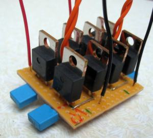
I didn't have a picture of a single bridge so the picture shows two on one piece of strip board. Ignore the blue capacitors for now, they are snubbers but let's concentrate on the diodes first. Each set of four MUR860's makes up one bridge rectifier circuit. Notice the orientation of the four diodes, and the wire links that join them up at each side. Compare this to the circuit diagram shown further up the page until you understand how the two are related. The strips of the strip board run at right-angles to those wire links and would short the two legs of each diode unless we cut the track between them. If you look at the picture of the underside of that strip board, you should be able to see the breaks in the copper tracks between the legs of each diode.
And here to make things even clearer (I hope) is the strip board layout looking at the strip board from above that is with the copper strips on the underneath of the strip board. As you should be able to see, this requires only four cuts in the copper strips, and only two wire links and four diodes.
![]() - You can buy a special tool which makes it easy to cut the copper strips on a piece of strip board. If you don't have one of these tools, a small drill can be used instead. But always make sure that the track is completely broken by testing with your multimeter.
- You can buy a special tool which makes it easy to cut the copper strips on a piece of strip board. If you don't have one of these tools, a small drill can be used instead. But always make sure that the track is completely broken by testing with your multimeter.
If you want to add snubber capacitors to your bridge rectifier I will leave that up to you. If you do, I suggest using small capacitors that have the same leadout spacing (that is the distance between their 'legs') as the MUR 860 diodes. That way, you can simply solder them to the legs of the diodes on the underside of the strip board as in the example above. The small caps are not polarised and can be soldered on either way round.
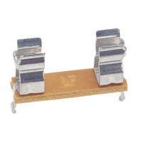
The final stage of the power supply is to add some reservoir (smoothing) capacitors, and secondary fuses (if you are fitting them). You could of course use a larger piece of strip board for your bridge rectifier(s) and add the capacitors and fuse-holders to that using either wires, or wire links . The important things to insert the reservoir capacitors with the correct polarity. If you get it the wrong way round, the capacitor is very likely to explode! In the case of the power supply described above we have two bridge rectifiers, both with a positive output and a negative output. You connect the side of the capacitor marked negative to the negative output, and the other side to the positive output. Your capacitors made be marked in a number of ways to show the negative terminal and a few examples are shown in the next picture.
Secondary fuse holders (of the type shown below) can be mounted on the same board as the bridge rectifier and reservoir capacitors.
But we are still not quite done! If you have not already done it, build the safety earth connector (shown in the shaded area in the diagram below) and connect it up to your power supply as shown. The connection to the 0v line should be made between the reservoir capacitors. When using two bridge rectifiers, the connection point is the mid point of a wire connected between the negative output of one bridge, and the positive out put of the other. I'd better show you that to be sure you get it correct.
If you use a single bridge rectifier, then the safety earth connection is to the centre tap of the transformer, or if your transformer has twin secondaries, to the track/wire that is joined to the two secondary wires that are joined together. See here for a diagram. (The 35A bridge is a standard bridge rectifier)
Testing
Yes, this is the part where it starts to get exciting. If you are new to this you will notice your heart rate quickening, and probably start to wonder why you ever started such an undertaking. But don't worry, everybody has been through this, and the fact is, if you have followed all the advice on safety, there isn't too much that can go wrong.
To make things even less risky, we are now going to build a simple device that can prevent a big problem if you have made a mistake somewhere in the power supply construction. For this item, you will need a:
- 40, 60 and 100 watt lightbulbs
- a suitable holder for the bulb
- Two push to make mains switches and suitable connectors (crimp on receptacles). Try and get two different coloured switches.
- an enclosure - make this plastic and you won't need to worry about earthing it.
- two cable glands of the right size for your mains cable
- a two-way terminal block
- one crimp on ring terminal and a suitable short nut, bolt and star washer
- a mains cable. In fact one of those cheap kettle leads would be ideal!
- Mount the bulb holder on the bottom of a suitable aluminium box.
- Mount the two cable glands, one in each end of the box.
- Cut the mains lead in two and prepare each cut end so that the three wires are out of the sheath and stripped about 6 mm of their insulation.
- Pass each cut end through a cable gland and fix the live wire into one side of the switch.
- Using an extra bit of wire, connect it to the other side of the switch and then to the bulb holder.
- Join the two neutral wires together in one side of the terminal block and then do the same for the two earth wires.
- Use another short length of the earth wire and crimp on the ring terminal. Now bolt that terminal to the case, and place the other end of the wire in the terminal block where the other two earth wires are joined.
- Wire the second push-to-make switch across the light bulb holder.
- Now check everything carefully and then screw on the lid of the box.
So you should have a box with a light bulb mounted on top (when the box is turned over) and a lead on one side with a mains plug, and a lead on the other side with an IEC plug. This is what you will connect to your power supply for testing it, instead of the usual kettle lead.
You don't have to understand how or why the bulb-tester works. Just accept that it is a valuable piece of insurance when testing your power supply. AndrewT supplies the following anecdote that illustrates nicely how the bulb-tester saved him a heap of trouble. This is a very powerful analytical tool that also prevents catastrophic failure. I had the polarity of a PSU to amplifier reversed. The protection diodes across the output to supply rails were now very effectively shorting all the available current from the PSU. No tracks burned, no semiconductor damage, no PSU damage and I had it running long enough to start measuring WHY I could see only 2Vdc output on each supply rail. During this time the bulb was glowing brightly but the transformer only had about 5 or 6Vac on it's input. Yes, even the most experienced people make mistakes. They are simple to make and sometimes you just don't spot them prior to applying power to a circuit. So get into the habit of always using the bulb-tester when you test a project, not just a power supply! To test the bulb tester:- plug one of the light bulbs in to the holder (it doesn't matter which one for this test). Do NOT connect the other end of the bulb-tester to anything.
- Now press the push-to-make switch button (that switches on the power - not the one that bypasses the bulb).
Now, go back over part of power supply in turn and double check that it done properly. Look out for any shorts, particularly to the metal case if you used one. Place a suitable fuse in the fuse-holder. It won't do any harm to check it first using your multimeter, as it eliminates another potential problem before you start.
It is suggested that you start your testing by placing a 40 watt bulb in the bulb-tester.
Make sure that your bulb-tester is NOT connected to the mains while there is no bulb in the socket, even momentarily while you change bulbs.
Make sure that the transformer is wired up correctly on the primary side but disconnect the bridge rectifier(s) because we are going to do this testing in stages.
STAGE 1 - with the bridge rectifiers disconnected, but the secondary wires of the transformer still connected to the terminal block, you can now make sure that you are getting the intended voltage from the transformer.
![]() - If something is amiss, it is obviously best to be able to turn off the power straight away. If you are holding both probes of your multimeter, you will need to put them down first causing a few seconds of delay that could be costly. Also by using a push switch for the bulb-tester, you will only have one hand free anyway. So what I do when testing is to take some lengths of wire with a crocodile clip at one end (I use a red, black and blue one to correspond with my wiring colours). I strip the other ends of the wires and then attach them to the terminal blocks. I then clip the clips onto the probes of the multimeter. Doing it like this I don't have to hold the probes, and can also sit back away from what I am testing.
- If something is amiss, it is obviously best to be able to turn off the power straight away. If you are holding both probes of your multimeter, you will need to put them down first causing a few seconds of delay that could be costly. Also by using a push switch for the bulb-tester, you will only have one hand free anyway. So what I do when testing is to take some lengths of wire with a crocodile clip at one end (I use a red, black and blue one to correspond with my wiring colours). I strip the other ends of the wires and then attach them to the terminal blocks. I then clip the clips onto the probes of the multimeter. Doing it like this I don't have to hold the probes, and can also sit back away from what I am testing.
Ok, so with your multimeter set to AC - remember that because it is AC coming from the transformer, not DC, and the voltage range set to 200volts, turn on the power (you have got the bulb tester connected I hope). The bulb in the bulb-tester should light up *. It will be bright at first (as it has all the power) and then it will dim quickly to a dull glow and then go off altogether (as the power supply consumes more power). *All this may happen so quickly that you don't see it light up but as long as the bulb doesn't say alight, things are OK. You should see a reading on your multimeter corresponding to the secondary voltage of your transformer. If you have no voltage, check:
- Did the light bulb light up? If not check the fuse in the mains plug. Check the fuse in the PSU. Check the wiring on the primary side of the transformer.
- Did you get a voltage reading that is different to the secondary voltage stated on the transformer? If so check the wiring arrangement on the secondary side of the transformer.
If the voltage is correct, and nothing is obviously wrong (usually smoke or a smell of burning) then press the push-to-make switch on the bulb-tester that allows full power to the power supply. If things are still OK, ie correct voltage and no visible problems, then repeat this process using the 60 watt, and 100 watt bulbs. If all is well go on to stage 2. If you encounter a problem at any stage of the testing TURN OFF THE MAINS POWER and investigate the problem before re-testing.
STAGE 2 - remove the crocodile wires from the terminal block and reconnect the bridge rectifier(s) In fact just add one at first! Now somehow connect those crocodile wires to the output of the power supply. I have some wires with crocodile clips on both ends for this purpose. You will need to have your reservoir capacitor connected on the output of the bridge rectifier to provide a load. If you don't you will not measure the correct voltage!
Now do remember to set the meter to read DC, connect it to the output of the bridge, sit back and turn on the power again. You should get a reading close to the transformer secondary voltage multiplied by 1.4. Not good at maths? OK check the chart below.
| Secondary voltage | DC after bridge |
12 | 17 |
15 | 21 |
18 | 25 |
20 | 28 |
22 | 31 |
25 | 35 |
30 | 42 |
If your voltage reading is correct (ie within one or two volts) of the target voltage), go on and connect the second bridge rectifier and test that. If it is not correct, disconnect power immediately and double check how you have built your rectifier bridge. If you cannot get it right, perhaps you should buy a ready made bridge and try that instead.
And that concludes the testing of your power supply. If you have the correct voltages, well done, and you can now connect your supply to your chip amp. But never connect a PSU to the amplifier (or what ever else it may be supplying power to) BEFORE you have checked that it is providing the correct voltage, and appears to be working without problem.
Addendum
In this section I will try and answer some of the other questions that may arise when building a PSU. I can't cover every option, I am now 58 and don't intend to spend all my remaining time on this project! If I don't cover something that you want to know here, please don't write to me, but go to the Chip amp forum at diyAudio and ask there (there is a sticky thread there relating to this guide).
Should I have the power supply in the same case as the chip amp, or having it in a separate enclosure.
How do I use a power supply in a separate housing?
How much capacitance should I put in my power supply?
What about snubber capacitors on the bridge rectifier?
Can I use a centre-tapped transformer with two bridge rectifiers?
I have a transformer but it has higher secondary voltages than can be used with the chip I have. can I use it somehow? (Regulated supplies)
![]()
Should I have the power supply in the same case as the chip amp, or having it in a separate enclosure.
The are pros and cons with each option. The transformer vibrates as was stated earlier, and the diodes can give of some interference (in theory at least) so this may be enough reason for you to want to keep them well away from your amplifier circuit. In practice however, many chip amps are built into the same case as the power supply without any apparent (or should that be audible) problem. Of course by having a separate power supply, you can make the chip amp very compact, although that could be offset by the need to find somewhere to place the PSU. You can see that as in a lot of case with building hi-fi, there is no definitive answer so you will have to decide what you want to do, or perhaps what you are able to do, considering your skills and budget.
How do I use a power supply in a separate housing? If you choose to go with a separate housing for your PSU, you will need to be able to connect it to the chip amp. This is done by a cable containing the necessary wires, and we call this cable the umbilical. How many wires you need in your umbilical depends on the type of PSU that you have built. In the example above, we used two bridge rectifiers so we will have two wires from each of those, and the earth wire, making a total of five. And that requires that we use what is known as a multipole connector or connectors. I usually hard wire the umbilical to the PSU and then plug it into the amplifier. Some choose to have the umbilical separate with a connector at each end. It really doesn't matter too much which way you do it.
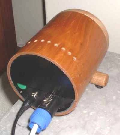
There is a wide variety of multipole plugs and sockets available but unfortunately for us, most of them are for carrying signal wires, and not the larger diameter wires that we want to use for a power supply. It's important when choosing a multipole plug and socket that you have room to get all your wires in, and be able to solder them without needing the skills of a neuro-surgeon! For all my chip amp projects, I have used Speakon plugs and sockets (as shown below). Although intended for connecting speakers, they are rated such that they are safe to use for the sort of voltages/currents that we will use with a chip amp. Sadly, the maximum number of poles is, so I am usually compelled to use two of them.
The length of the umbilical doesn't matter too much proving you don't go crazy. A metre should provide you with enough options in placing the PSU and amp where you want them But I would say that anything up to two metres long will be OK as long as you have some capacitance in the PSU case (as you should even if it is only a few micro farads). I use four-core mains cable for my umbilicals after getting fed up with constructing my own multicore cables.
How much capacitance do I use in the power supply? This subject is hotly debated topic amongst chip amp builders. If you are new to chip amp building I suggest the following arrangement. About 10-100 uF after the bridge rectifier, and 1000 uF on each (power supply) pin of the chip amp. If your speakers are a difficult load, you will need much more capacitance than this. But if you put say 10,000 uF after the rectifier, you will almost certainly notice that the chip amp loses some of its magic. It's another hi-fi compromise, trading some good mid-range, for better bass. There are a couple of ways around the compromise though. Either go for the snubberised supply as shown here, or a regulated supply as described here. But be warned, both these types of power supply are more complex than the basic supply described in this guide. Only try and tackle them when you have gained confidence and experience by building the basic version first!
Of course, you are free to experiment with any amount of capacitance you want to try, you don't have to stick to the figures that I suggest. As with all polarised capacitors though, make doubly sure that you have connected them with the correct polarity, and make sure that they are (voltage) rated high enough to take the voltage passing through them.
What about snubber capacitors on the bridge rectifier?
You will find those who say they work, and others who report that they make no difference. Why? Because you must have the correct value capacitors for the circuit that they are used on, which includes the transformer windings. A recent post on the diyAudio chip amp forum suggested that it is just as beneficial to place a single small capacitor in parallel with the transformer winding immediately before the bridge as shown in this diagram.
This is in effect using just one snubber cap instead of four. But what is more interesting is that the poster suggested appropriate values for the capacitor(s). This suggestion was developed into a more comprehensive spreadsheet that you can download.
Can you use a centre-tapped transformer with two bridge rectifiers?
This is a frequent question on the forums so I will deal with it here. Have a look at this diagram again of a centre-tapped transformer, and one with twin (dual) secondary windings.
Can you see that both transformers have two secondary windings? But with the centre-tapped transformer, one end of each winding has been joined together to make the centre-tap. Now, if you can separate those two ends, you have a transformer with dual secondaries, and you can therefore use two bridge rectifiers. Once again, you need to ask yourself if this is a job that you can safely do yourself. It involves cutting away a little of the insulation material over the windings where the centre-tap wires exit. The material maybe cloth or some kind of plastic and should be able to be cut with a sharp knife. But be very careful. The windings are made from enamelled wire and you could easily break that enamelled coating and remove the insulation between the windings. However, if you can remove the (outer) insulation, and find where the two windings are joined, you can then separate them. You may then need to add new leadout wires. If you do, try and colour code the leadout wires such that you know which wires form a pair, ie one winding. Of course, if you forget to do this, you can also check the lead out wires with your multimeter to see which ones are from the same winding.
As always, if you don't feel completely confident to do this job, be sensible and buy another transformer with dual secondary windings. It may work out cheaper in the long-term!
I have a transformer but it has higher secondary voltages than can be used with the chip I have. Can I use it somehow?
The only really practical way to use it is to build up a regulated supply where you can drop some voltage across the regulator. There is a limit to how much voltage you can drop because the regulator gets hotter with the more voltage that it drops. I would recommend dropping a maximum of 10-12 volts only. You can read about a regulated chip amp power supply here.
There are some advantages to using a regulated supply other than dropping voltage. In theory they should provide a much smoother supply, but sometimes this can appear to take the life from an amplifier. It's really a question of trying it and seeing if the sound suits you. I wasn't too keen on the LM338 regulated GC but I love (and still use) the discrete regulated version designed by Pedja Rogic.
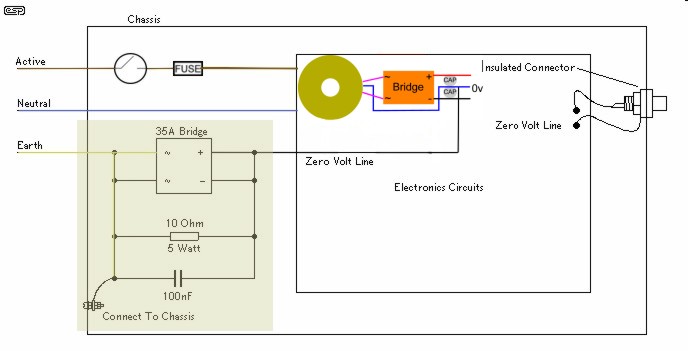
Ground lift safety earth connection for chip amp power supply (with single bridge rectifier).
Last update: 24th November 2019 - Copyright © 2009 - Author Nick Whetstone