Hung up on DIY hi-fi?
Then welcome to

Building a Gainclone (chip amp)
with a snubberized PSU.
(Please read carefully before
asking Carlos questions)
![]()
![]()
Decibel Dungeon
Introduction.
Please note that I have used Carlos' own description of 'snubberized' for this type of PSU. You will also see it referred to as snubbered, snubbed and probably several other similar sounding names. In all cases we are talking about the PSU(s) described below.
The beauty of the Gainclone concept is its simplicity. Even the power supply is simple with a couple of 1000uF capacitors on the chip's power supply pins. I have found it to work very well but then all the speakers that I have tested my GC's with, are easy to drive, high efficiency types.The circuit.
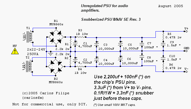
Circuit diagram of snubberized Gainclone PSU by Carlos Machado.
- You should recognise the transformer which is shown above with (two) separate secondary windings.
- The transformer is followed by the usual rectifier bridge to convert AC into DC.
- R1 is a resistor and it's purpose is to allow the large capacitors to 'drain' their charge back to the zero volt rail. This is a safety feature as larger capacitors can hold their charge for quite a time after the power is removed from the rails. This could be potentially dangerous if you are working on the circuit soon after you have switched off the power and (wrongly) think that it is safe to touch the capacitors or anything connected to them!
- Next, we have the first of the large capacitors, in this case 4,700uF.
- The resistor in series with the 4,700uF and first 10,000uF capacitor forms a smoothing filter.
- After another pair of 10,000uF capacitors, there is a 100nF film capacitor. This 'bypasses' the larger capacitors.
- Then we come to the actual snubber network, comprising the 0R47 (0.47 ohm) resistor and 1.5 nF film capacitor.
- Carlos prefers to remove the standard 1,000uF capacitors from the pins of the chip and use 2,200uF instead and bypassed by another 100nF film capacitor. But again, he uses a snubber network on these, comprising of the 0R1 resistor with a 3.3nF film capacitor.
- Lastly a 3.3 uF film capacitor is placed across the positive and negative voltage pins of the chip.
Please note that although Carlos has generously shared his snubberized circuits with us, he is understandably not revealing all his secrets. So please do not ask him how he calculates the values for his snubberized PSU. The ones published by Carlos, here and elsewhere on the Internet work well but he is too busy to go into discussion about alternative values!
If you want to read more about the un-regulated hi-cap (snubberized) PSU you can find the original diyAudio thread here.
The (LM338) regulated circuit.
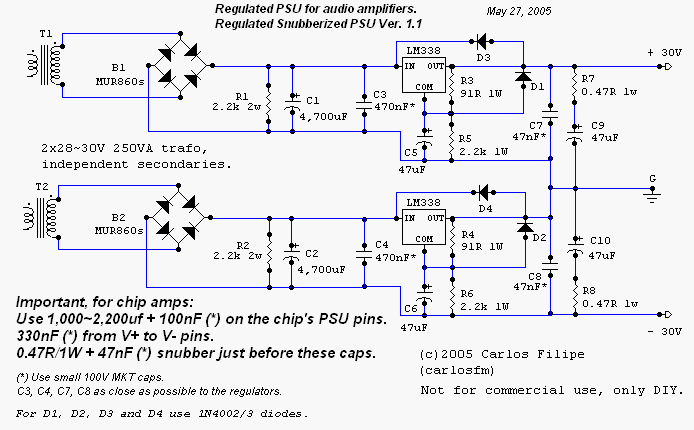
Regulated, snubberized Gainclone PSU by Carlos Machado.
Update - August 2005.
Carlos has been at it again (does he ever sleep?) tweeking the snubberized circuits for the Gainclone. Here are the latest circuits:
Snubberized Gainclone PSU by Carlos Machado.
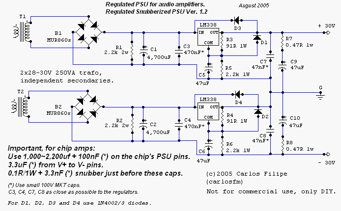
Regulated, snubberized Gainclone PSU by Carlos Machado. Read all about it here (diyAudo forums).
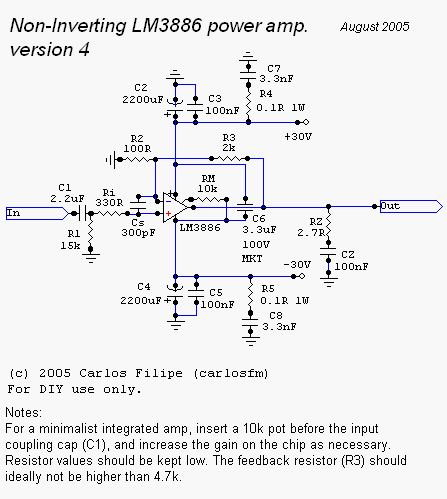
Snubberized LM3886 Gainclone circuit by Carlos Machado.
My opinion.
I have only tried the original version of the snubberized PSU and found that it made a small but significant improement to both the LM3875 and LM3886 inverted Gainclones that I have. I then added it to the LM3875 IGC that I use to drive my subwoofers. That already had 10,000uF capacitors in addition to the smaller capacitors on the chip pins. I simply added the bleeder resistors, the 100nF cap and the snubber (1R with 100nF). This made a much larger improvement so I can only assume that the subwoofers (transmission line with Seas P21 drivers) are a more difficult load than my main speakers! As ever, the advice is to try this for yourself and see. It doesn't cost too much and you may find your Gainclone raised to another level!Last update: 4th July 2012 - Copyright © 2005-06 - Author Nick Whetstone