|
Decibel Dungeon
|
|
|
|
Nothing stays the same with technology and hi-fi is no different. With DIY hi-fi things probably move on even faster than in the commercial sector as thousands of enthusiasts around the world combine their ideas on how to improve on a given design!
|
|
The Gainclone has, not unsurprisingly, due to it's simplicity and low cost, become a huge phenomenon in the world of DIY hi-fi. However, as always, methods of improving the design have come along to provide an almost bewildering number of options for the new builder. As ever, I recommend that if you have not built a GC before, the best thing is to build the basic version (without buffer etc) and only then try a buffered or regulated version.
|
|
First we had the buffer (often combined with an LPF), or I should say buffers built from valves, opamps and discrete transistors. Now we have the regulated power supply which was initially intended to allow the use of larger power supply capacitors which would (hopefully) improve the bass performance of the Gainclone without any deterioration at other frequencies.
|
LPF - Low pass filter designed to take a little bit of the extreme high frequencies from the signal to improve the sound.
|
|
Please note, that the regulated supplies as discussed on this page will suffice for two channels of a stereo amplifier.
|
| Site menu
Page menu
|
|
|
One of the first (if not the first) designs for a regulated PSU for the GC appeared on the site of GC guru, Pedja Rogic. It is shown below.
|
|
|
|
It's on this design that my own regulated GC supply is built although I did make a few changes.
|
|
This is a fairly standard power supply using a commonly available three-terminal regulator, the LM338. The first half of the circuit uses a transformer with two secondary windings 'feeding' twin rectifier bridges. Pedja used SB560's but you can choose your favourite rectifier diodes or even use ready made bridges.
|
|
Instead of connecting the rectifier bridges to the decoupling caps on the pins of the amplifier chip, as is usual with a chip amp, some large reservoir (smoothing) caps come next in the circuit. A pair of 4,700 uFs are fine, or a single 10,000 uF. The LM338 is placed as close to the reservoir caps as is possible while allowing them to be placed on their heat sinks. A pair of resistors set the actual output voltage, some caps are added for stability and a pair of diodes are used to protect against possible damage from reverse voltages that may occur when the power is turned off.
|
| Site menu
Page menu
|
|
|
So what do you need to build a regulated PSU for your Gainclone?
|
|
It can be seen clearly that the regulated PSU uses more components than the basic GC PSU with the reservoir capacitors and regulators accounting for a bulk of the extra cost. Fortunately, I had some spare 10,000 uF capacitors lying around which meant that I could try the regulated design without a large outlay. The LM338 regulators are fairly common although their price can vary quite a bit (1 - 2 UKP) so it is a good idea to shop around if you have the choice. The other capacitors, smaller value capacitors, protections diodes and resistors are all common items and easily obtainable if you don't have them in your parts box. 0.25 watt rated resistors are fine but you can used 0.5 watt if you prefer. IN4002 diodes will do for the protection devices and you can make your choice of capacitors according to how much that you like to spend on such items.
|
|
So my regulated PSU differed from Pedja's design as follows:
- I stuck with the tried and tested MUR860's for my rectifier bridges. The transformer/rectifier bridge section of the PSU is housed in a separate case and connected to the amplifier via a half metre umbilical lead.
- I used 10,000 uF caps instead of a pair of 4700 uFs. Some may argue that two smaller values are better than the 10,000 uFs but the ones I used are the Slitfoil types which negate the problem of the higher value capacitors. You can read about the Slitfoils (and the still better T-caps) on the DNM site.
- On the advice of another builder, I put a 0.47 uF (polyester) cap from the input pin of each regulator to ground. This cap should go right on the input pin.
- I used a 47 uF cap to bypass the lower arm resistor. This is probably a bit higher than needed and anything between 10 uF and 47 uF will suffice.
- I used the second protection diode which goes across the adjust and output pins of the LM338 (as well as the one across the input and adjust pins). It is good practice to use this diode. IN4002 types are adequate for this job.
- I used 0.33 uF polypropylene caps on the output of the regulator circuit. I happened to have these in my parts box but other builders have used 0.47 uFs.
- On the pins of the chip (LM3875) I have left off the usual 1000 uF's and used 100 uF instead. It is (apparently) worth trying different values for this part of the circuit, ranging from 33 uF to 120 uF. I stuck with Panasonic FC types as I rate them highly.
|
|
It is important to make sure that you have the LM338 regulators on adequate heat sinks! Please note, in the picture of my regulated PSU below, the heat sinks are actually copper mounted on 6mm thick aluminium. In practice, although I am dropping nearly 10 volts across the regulators, the heat sinks do not get hot.
|
| Site menu
Page menu
|
|
|
The LM338 is an adjustable voltage regulator. This means that we have the opportunity to set the output voltage exactly how we want it with a couple of provisos.
|
|
First we must remember that the LM338 needs at least 3 volts more on its input pin than on its output. So if your voltage rails from the rectifier bridges are 37 volts DC, the maximum output voltage will be 34 volts DC.
|
|
Second, we have to remember that the amplifier chip has a minimum and maximum voltage input so check the relevant data sheet for the chip that you are supplying power for.
|
|
Let's say that we start out with a transformer that has secondary voltages of 25-30 VAC, that will produce around 37 volts DC after the rectifier bridges. The maximum output voltage will therefore be 34 volts.
|
|
We can set the voltage rails for the amplifier circuit by the choice of resistors used to adjust the output of the LM338's. If you are new to this sort of thing, I suggest sticking to 120 ohms as the resistor that is connected to the output pin of the regulator. This resistor is often called the 'upper arm resistor' (UAR). Assuming that you do that, here is a table of output voltages for the other resistor which you may have guessed is called the lower arm resistor (LAR)!
|
|
| UAR | LAR | V out |
| 120R | 2K2 | 24v |
| 120R | 2K4 | 26v |
| 120R | 2K7 | 29v |
| 120R | 3K | 33v |
| 120R | 3K3 | 36v |
|
|
If for some reason you want to use another value for the UAR, you can calculate the output voltage for any combination of UAR/LAR by downloading and using this simple EXCEL spreadsheet.(Zip file) But do not deviate too much from the 120R value as this affects the amount or current drawn through the regulator.
|
| Site menu
Page menu
|
|
|
I'll assume that you know how to make the rectifier bridges and connect them to the transformer. If you don't then may I suggest that you make a 'basic' GC first and come back to this section when you have it working OK.
|
|
This section of the PSU can be in the same case as the rest of the circuit or in a separate case; it doesn't matter too much either way!
|
|
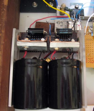
What does matter is that you remember the following. Keep your main PSU caps (4,700/10,000) as close to the regulators as you can get them. And keep the output of the regulators as close to the pins of the amplifier chip(s) as you can get them. There is a small practical problem here and that is how to get adequately sized heat sinks onto the regulators that don't get in the way. Fortunately, as I found you can make up some reasonably compact heat sinks that will do the job. Mine can be seen in the picture below and are made from a combination of copper strip and 6 mm aluminium bar. The LM338's are bolted onto these heat sinks with a little heat sink compound between them and the heat sinks. But please remember that this will put a voltage onto the heat sinks so none of them must touch the others or anything conductive!
|
|
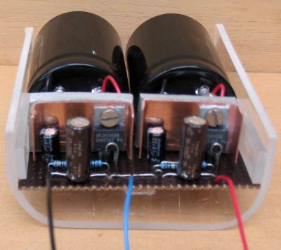
(The modules are pictured here with 220 uF caps on the output. These were later replaced by the 0.33 uFs)
Protection diodes are IN4002 type.
|
|
As you can see, I managed to get the whole LM338 circuit quite compact although it meant that adding the extra caps on the input pins required soldering them underneath the PCB!
|
|
Stripboard is ideal for a smallish circuit like this. Here is the layout that I used (well modified to include the extra caps).
|
|
This is my suggested layout and should be fairly self-explanatory.
Protection diodes are IN4002 type.
|
|
Note that I located the two protection diodes vertically to save space. It is (obviously) important to insert the diodes the correct way around. The cathode of the diode between input and output pin is on the input pin (see Pedja's circuit above) and the cathode of the other diode (connected between the adjust pin and the output pin) is on the output pin. The cathode is always indicated, usually by a silver ring on one end of the diode or by the letter K (cathode)!
|
|
As always, when constructing a compact circuit, take care to avoid short circuits (particularly with the metal heat sinks if they are not insulated from the regulators.
|
|
It is also worth mentioning here that the LM338 is available in two packages. The TO-220 is somewhat cheaper than the TO-3 version. The latter though will handle more power due to a larger contact area with its heat sink. Generally the rule is: if you use a regulator circuit for each channel, the T-220 if fine. If you use just one module, you will be better off using the TO-3.
|
| Site menu
Page menu
|
|
|
It can be quite confusing trying to understand the PSU options for a basic Gainclone so here is some help with the various options that you have for a regulated supply.
Click on the diagram for the full-size version.
|
|
Just remember the following points when deciding on which option you will go with.
- Which ever option you decide on, you must have a transformer with twin secondaries, ie it will have four wires, not three.
(If you have a transformer with just three leads, you may be able to open up the protective cover, find the ends of each winding, separate them and add another leadout wire. Please only attempt this modification if you are confident that you know what you are doing)
- You will need a minimum of two rectifier bridges.
- If you use just one regulator circuit for two channels, you must have adequate heat sinking for the regulator chips and preferably use the TO-3 versions.
- If you use a regulator circuit for each channel as in the lower picture, you must have a pair of rectifiers for each regulator circuit as shown. Please see this post of diyAudio for the reason. You can however still use a single transformer providing that it has a sufficient VA rating.
|
| Site menu
Page menu
|
|
|
The regulator module connected to the chip. Note the smaller caps on the chip supply pins!
|
|
So how does it sound? Well, by the time I eventually finished my regulated supply, there were quite a few reports on the forums from GC builders who had tried it before me. Only one of those builders thought that the regulated supply didn't improve the sound over the unregulated PSU.
|
|
My audition indicated that there was indeed a clear improvement, not just with the bass but right across the frequency range. I still have some more experimenting to do with the size of decoupling caps on the supply pins of the LM3875s but I am sure that I will be using a regulated supply for my future GC's.
|
|
One other observation is that the heat sinks got quite a lot warmer than my unregulated GC using the same circuit. It did not get to the stage where the protection circuit shut the chip down but if this is usual for a regulated supply, I would suggest the use of larger heat sinks to compensate.
|
| Site menu
Page menu
|
|
|
As you can see, I thoroughly recommend trying the regulated PSU. It takes the GC one step higher. The LM338 is not the last word in regulators. There are (supposedly) better ones and Pedja found that a discrete regulator was better again. You can check out what he has to say on the subject by visiting his archived pages. Will I build a discrete regulator? Yes, I think that I will!
|
| Site menu
Page menu
|
|
|
3rd June 2005.
I have now built the snubberised version of the LM338 regulated power supply as designed by Carlos Machada.
|
|
Basically, I modified one of the regulator modules described above and added the components that are shown below.
|
|
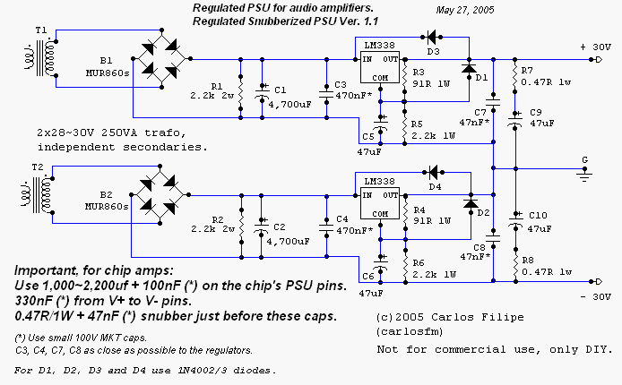
Regulated, Snubberized Gainclone PSU by Carlos Machado.
|
|
The changes that I made to the circuit are as follows:
- Transformer is a 225 VA with twin 25 volt secondaries.
- The main reservoir capacitors are 10,000uF Slitfoil types.
- I used 1,200uF Panasonic FC capacitors on the voltage pins of each chip.
- The output voltage of the regulated supply is +/-27 volts.
|
|
Notes on construction.
As stated above, the actual regulator modules were the ones built for my original LM338 regulated supply. I only had to change the capacitors on the output and add the snubbers. It took much longer to remove the small capacitors and add the components to the chips! There is quite a lot to get in a comparatively small space but it can be done.
|
|
I would suggest adding the snubbers to each capacitor before soldering them to the chip. Get the smallest 0.33uF film cap that you can and it will fit neatly between the leadouts of the capacitors on positive and negative pins.
|
|
I used the method Carlos suggests of joining the power ground stars of each amp with a thick piece of wire and then joining the centre points of the wire to the ground (0v) connection of the regulated PSU. You should be able to see that in the picture below.
|
|
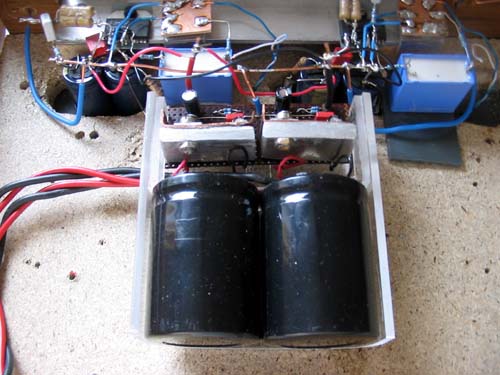
My regulated, Snubberized Gainclone.
|
|
|
|
The results.
It had been quite a while since I listened to the regulated supply. But even so, I could detect a clear improvement using the Snubberized version. Just about everything is improved, bass, sound stage, depth, and timing. The amplifier seems to have more control over everything that I have played through it. And this was with only one regulated supply instead of the two (one for each channel) that I used before!
|
|
One thing that surprised me was that the amps didn't run anywhere near as warm as they did with the 'plain' regulated supply. Was this down to the snubbers, the caps across the supply pins, or just using one regulator module instead of two? I have no idea, and no inclination to waste time finding out! The amp sounds fantastic, is 100% silent when not playing music, has no noises at power up or power down and runs cool. So I won't be changing anything.
|
|
Is this the best Gainclone yet? Well, almost as I still feel that the GC with SMPS just beats it in terms of clarity. But if you want a Gainclone PSU that will work with just about any speaker load, and sounds fantastic, then build this regulated, snubberised PSU. You won't be disappointed!
|
| Site menu
Page menu
|
|
|