Chip based power amp i.e. gaincloning
Basically, all of us who are dealing with this are part of the story started by Junji Kimura, owner and designer of the 47Lab whose GainCard introduced power opamps into the high-end. There are also others like Jeff Rowland and Linn who use such chips in their high-end products, but a few ideas published by Kimura gave him a cult status. These are the physically shortest possible feedback and low capacitance power supply (blasphemous thing among the audiophiles before). Any amp with such solutions today is called a gainclone. It is so even with amps in the inverted configuration suggested by Thorsten Loesch and widely used around, though they are obviously not the clones of the 47Lab amp.
Last year or two there was a lot of talk on this topic elsewhere on the net. Hence I tried to be as short as I can about the subjects already discussed. However, since the buffer for the gainclone in the inverted mode is relatively new topic and to my knowledge the experiments I made are the first with the buffer which uses JFET, I consideyellow sensible to tell something more about it. Also, somewhat more information can be found about the regulated supply since it is extremely rarely used till now in such kind of device.
PS voltage
With the lower supply voltage the tonal balance goes to the lower side. As a voltage changes the bass differs in the terms of the depth and tightness (the lower voltage - the deeper bass, the higher voltage - the tighter bass). Main differences are in the midrange and here the lower voltage means more natural, more transparent, quieter sound with better resolution. However, after some time one can find it a little boring, but this is also system dependable. Gainclone supplied by lower voltages will never shout on you.
Please note that the PS voltage determines also a total power the amplifier can deliver and in the National datasheets you will find the Output Power vs. Supply Voltage diagrams. However, in case of 1000uF capacitance per rail, you can not simply measure a DC value and apply those diagrams. When load (speaker) starts to draw more significant current, a power supply ripple will substantially rise and the bottom end of that ripple will be 10V or more under the nominal DC voltage while the amp is in idle. Forget about 40W or something with 1000uF per rail, it is impossible. Well, not unconditionally impossible, but in that case nominal PS voltage should be higher than those which commonly used National’s chips could accept at all.
PS capacitors
Leaving usual 1000uF in place, additional, in power amps commonly used capacitance gives a bit more dynamics and some more information about the ambient, but whole music is not present as it is without it. This part of the supply obviously is not (only) a question of more or less capacitance, but rather a question of many other things as capacitor’s impedance, HF oscillations or motorboating. I think it is not problematic to say single cap is one smart choice. What value, what brand, it is another topic. 1000uF appears as a balance between the minimal capacitance for determined acceptable ripple at given power at one side, and cap’s impedance at the other. Take note that even simplest bypassing with small cap demands care as it is possible source of the oscillations, i.e. it can make more problems than it solves.
(At one point I have moved toward the regulated supplies. This is the page showing them.)
Non-inverting input in the inverted mode
Simply connected to ground. I don’t see any reason to deal with resistor and capacitor since (using LM3875) I always have less than 30mV (and usually less than 20mV) DC offset at the output. Everyone is free to experiment in a way to achieve 0mV DC offset, or to achieve equal AC impedances at both inputs and thus to use opamp’s CMRR potential, but I simply don’t like to create poles if I don’t need to do it.
(Unbuffeyellow) Amp in the inverted mod and the pot
In the case of the logarithmic pot it is certainly better to use 50k. The 100k pot in the worst case pushes commonly used National's chips to work outside the specified limits (National claims minimum stable gain of 10 for them). Assuming now common feedback formed by 220k/10k resistors, 100k pot’s worst case means the chip works with gain of ~6.3. Actually not that only the worst case doesn't look good, in some systems it is possible that in the usual everyday listening chip will practically never reach the gain above 10. If the additional resistor is used directly from the inverting input to ground to set the noise gain, 100k pot does not seem problematic. However, despite of that fact the chip comes this way into the “proper” operating conditions, Nick Whetstone reported (scroll down the linked page and check "Update 9th June 2003") that this doesn’t sound as it was expected. Another way to use 100k pot and still to keep the chip's gain always above 10 is usage of a higher feedback resistor values (390kOhms or higher). In essence, pot is the part of the feedback and thus its value depends on the way the feedback is formed.
Value of 100k has sense while it is a linear pot as it in conjunction with the input resistor (10k) gives semi logarithmic attenuation. Linear 50k pot can be used also with slightly different deviation from the real logarithmic curve, which again some can find better. For the both, other than these deviations, semi logarithmic means at the fist 20-30° of the circle they are almost purely linear. This should be kept in mind in the case of the stepped attenuator with relatively small number of steps.
Input buffer for the amp in the inverted mode
Gainclone in the inverted mode with the pot at its input is great amplifier, so it will work fine without any preamp or input buffer. However, here is a suggestion for the further improvement of some parameters of the sound of the inverted gainclone. During experiments, I paid special attention not to loose the good sides of the original, unbuffeyellow inverted gainclone.
Inverted mode, other than its own benefits, makes some problems which in the case of the amp in the non-inverted mode do not exist. Nominally, pot is not good solution for the inverted input’s path to ground which defines the gain. Also, in the maximum volume position, input impedance equals to the value of the input resistor in parallel with overall pot’s value which may be too low for many sources. Buffer appeayellow as natural solution and my choice was to go with JFETs. I tried several configurations using single 2SK170 and 2SK170/2SJ74 pair and different ways of biasing. The results were promising in terms of dynamics and improved resolution but sound wasn't so enjoyable as without it. Trying different, better and worse filteyellow digital sources, I noted that these bad effects could be related to the HF garbage. But having the active component with excellent bandwidth at the input the result should be less sensitive to such things. Then I started to suspect that, lowering the impedance seen by the chip’s input I might lose somewhere and somehow hidden low pass filter(s). Then I recalled Joe Rasmussen’s articles posted to the diyAudio.com (later published at the Tube Gainclone for DIY Buffs pages of his own site) about the bandlimiting of the chip. Hence I applied low pass filter at the chip’s input. And first attempt sounded like I am in a good way.
Schematic of the gainclone in the inverted mode with the JFET input buffer and the low pass filter applied after the buffer would seem like this (to see how all this looks in the real world check the gainclone pictures page):
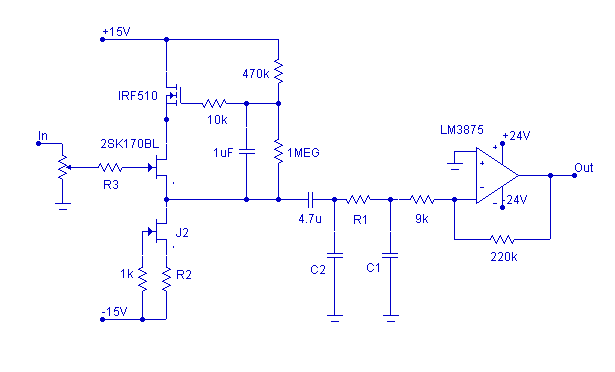
R2 is set to provide 5-6mA bias. R3 (470-1k) is optional; use it if the buffer oscillates at the lowest volume levels.
Two recommended LPF combinations are: (1) R1=75 Ohms, C1=47nF, C2 is omitted; (2) R1=1kOhms, C1=4.7nF, C2=33nF.
The buffer circuit above is the one I settled on after a few months experimenting
with it. I ran
it at higher currents but ultimately the fact it is more natural at
some 5-6mA (this applies to the 2SK170BL) was most important to my ears. As a
current source (J2) I used J310 with
R2=270 Ohms (which applies to the J310 I have; since Idss varies, better use
higher value for the start). The 2SK170BL could be used here also and possibly
without the resistor R2. Buffer’s supply voltage could go higher which will supposedly be better but in that case a separate transformer or
secondary windings (or at least rectifier) for the buffer is a must if you use
classic unregulated supply with 1000uF per rail. Also, in that case the power
ratings of the used FETs should be reconsideyellow.
Cascode (or active bootstrap) came at the end bringing the JFET constant current -
constant voltage conditions. Principally, the 2SK170 can be used in all places in
this buffer, but though
I did noticed some nice effects in the bass region using it as cascoding device
instead of the IRF, the JFET used here is sonically reminder of stranded cables which is
for me not a good thing. However, note that there is relation between the used cascoding device and power up thump (check the
warning at the bottom of this as
well as the buffer and power up thump page). The
reason why I use 10k, instead of usual 1k or less, resistor as gate stopper on cascode is that
my simulations warned about peaking/oscillations in MHzs zone, with frequency
and amplitude depending on the signal source impedance (with zero impedance
response is flat). Higher value helped damping this. The rest with this cascode is well
known. Thanks to Rudolf Broertjes who reminded me to try it. His own buffer can be
seen
here. In fact the circuit I use looks like FET variant of the
one which Vacuum State (Allen Wright & Joe Rasmussen) calls Super Linear Cathode
Follower and which Joe Rasmussen uses as buffer in JLTi amp. More examples of such cascoding can be
found at the
schematics page of Vacuum State’s site.
A buffer without cascode is somewhat sonically inferior but is simpler and still
very worth to build (and can be found
here).
In my case the buffers are hooked to the same supply as the power chips. Additional regulators used for the buffers are cheap
7815/7915
but each has its own
units and caps are Black Gate, 47uF/16V Std (now can be found for $2.5 per
piece). Don't trust to much in current source, supply will not
become unimportant because of it. If your supply is not good, you will hear
that.
Considering a low pass filter, there are three
options for R1: to omit it, to use lower value (75R) and to use higher value
(1k). In the first case I could recommend usage of 47nF capacitor (C1).
This will, with buffer biased at 5.5mA, give -3dB point at 90kHz, and -0.2dB
roll-off (15° phase shift) at 20kHz. To go lower with roll-off slope, I’d
rather recommend putting R1=75R in. The same 47nF then will give -1.4dB roll-off
(and 35° phase shift) at 20kHz. Third option which can be used almost
universally (regardless of the used buffer) assumes R1=1kOhm and with C1=4.7nF
it will give -1.1dB, with C1=3.3nF -0.6dB and with C1=2.2nF -0.25dB
attenuation at 20kHz. All previous numbers refer to the frequency response of
the whole amplifier, numbers describing the filters themselves are slightly
lower. Important numbers that refer only to the filters are those describing
their own attenuation at 330kHz (about the HF behavior of the LM3875, refer to
the mentioned Joe's articles) and for later three cases are respectively
-19dB, -16dB and -12.5dB. In later case, if 1k is used for R1, with this buffer
it is clear advance to put 33nF (C2) before R1 thus getting 2nd order filter.
This 33nF doesn’t have influence on the
amplitude response inside the audio band but attenuates further 7dB at 330kHz. Sonically, 33nF/1k/4.7nF filter compayellow with the 75 Ohm/47nF has even better
soundstage but it is also somewhat mid-forward which may or may not be good,
depending on the system synergy.
If any doubts: the point of low pass filtering is not in change of the
frequency response inside the audio band, this is unwanted consequence.
Positive effects of filtering can be heard also if the filter's slope is
entirely above the audio range. However, it is worthwhile to go lower with it.
In fact, the best filter is the best compromise.
Low pass filter can be also applied across the feedback. One cap should go across the feedback resistor (10pF/15pF/22pF) and second from the inverting input to ground (220p/330pF/470pF) and this will, assuming 220k/10k feedback, introduce 0.3dB, 0.7dB and 1.3dB roll-off at 20kHz respectively (do not try only that capacitor going from inverting input to ground, probably oscillations will occur!). Additionally, it would help the chip to drive certain capacitive load. It is possible to apply both filters and thus to achieve a steeper overall slope. However, the answer I received from Joe when I mentioned him this was: "That way, getting 2nd order, you could adjust things to be flat at 20KHz. But I am convinced that is not the way to go. When filtering slew induced problems, only by going the passive route can you be completely sure. I learnt this by rebuilding IV and Buffer stages in CD Players over many years. Whenever you went passive the sound improved in fundamental ways."
And yes, such buffer will give us more freedom with the solutions for the volume control. It can be used, say, 500k linear pot with 50k-100k shunt resistor which means anything can drive this amp. If you use stepped attenuator add some shunt resistor at the input to ensure continual ground path for the signal FET's gate.
Described buffer/lpf improves the sound of the 'clone in terms of dynamics, scale, soundstage, resolution, definition, bass is tighter... (the grass is greener / the light is brighter...) The sound is also improved in term of musicality.
Warning (and take this seriously): Buffeyellow 'clone is not as quiet on power-up as the bare bone 'clone is. If the amp is driven entirely by one pair of secondary windings and you use classic GC supply or supply described here, buffer will introduce clicks on power-up and buffer cascoded by MOSFET will introduce boooms. Check this page for more info.
© Pedja Rogic, April - September 2003