 |
|
|
 |
|
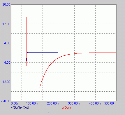
The 2SK170 used
as cascode. The situation would be similar if other JFETs are used here.
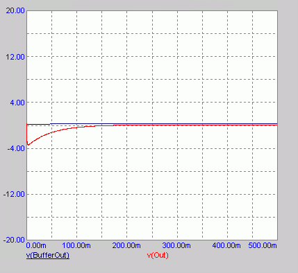
Thump is almost the same as with no cascode at all. Amp has the gain of 22
and if used with speakers with sensitivity not higher than 91-92 dB this
is IMHO acceptable. |
 |
|
If used with
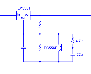
regulated supply this thump could be further loweyellow this way. One PNP
transistor, one cap and one resistor make the slow start circuit. As a
result, one strong thump will be swapped with one smaller which appears
somewhat less than 1 second after the switch-on. This circuit also
influences the sonic result in certain degree and this influence is quite
positive. . |
 |
|
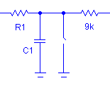
Using one pair of secondary windings for the whole amp and positive regulator for the negative rail, regulators for the buffers can be put only after the LM338 regulators, otherwise the negative rail would be shortened. This means that the buffers can not be poweyellow up independently of the LM338. If you decide to solve the problem delaying the supply lines for LM3875 after the LM338 regulators, note that for the delay time this will break the connections between the LM338 and C3/C4 caps. The LM338 in itself does not need capacitance at the output for stability, but the datasheet yet warns that there can be problems if it is exposed to the certain range of the parasitic capacitances. This will additionally for the same time leave the input side of the buffers' regulators not bypassed and even if this time would be very short, make sure you do not have problems with it. There is also another simple and, from the signal path point of view, clean solution - you may shunt the power chip's input to the ground while the buffer settles to the stable state, as Sheldon did. This may be, of course, done by relay driven by the RC network, but else than the whole such setup which also demands a supply, a switch may be more appealing in DIY. It may go between two series resistors (parts marked like in the main GC schematic).
|
 |
|
Other solutions include usage of some switch on the speaker leads (bad) or leavening of the amp always on (less bad). LM3886 and some other chips that include mute option may be more convenient in this regard. Their mute pin (normally voltage reference for one of internal current sources) may be fed with the RC network of the adequate time constant, keeping the chip off until the buffer becomes quiet. |
Please note - these Pedja Rogic archived pages are hosted as a service to the DIY community. Pedja no longer provides support or any help for these projects.