Hung up on DIY hi-fi?
Then welcome to

Building a Gainclone (chip amp)
with T-network feedback.
(With thanks to Franz G and Joe Rasmussen)
![]()
![]()
Decibel Dungeon
Introduction.
Nothing in the world of technology stands still for very long and even something as simple as the Gainclone develops at an amazing pace!
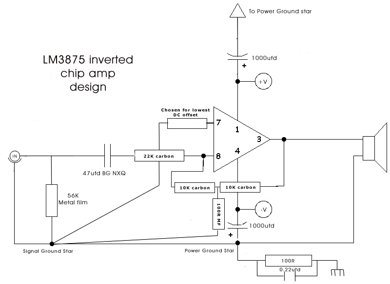
The T shape of the resistor network is quite apparent!
Resistor values
You can see in the above circuit diagram that I used the following resistor values (with the LM3875 chip):
- Input - 22K
- Output to inverting input - 10K and 10K (in series)
- Junction of series feedback resistors to signal ground - 100R
- The value of the resistor from non-inverting ground to signal ground will vary according to the chip that you use and will even vary between chips of the same make and model!
- Adjust the trim pot so that it is about 10K and then solder it between NI and signal ground. Power up that channel and measure the DC offset across the speaker terminals.
- Adjust the trimpot and remeasure the offset.
- Continue like that until you get close to 0 mV offset.
- Measure the resistance across the trim pot and find a resistor as close in value as you can.
- Solder the resistor in place and recheck the offset.
Why use these values?
The values that I have used in the above example were suggested by Joe Rasmussen after a lot of calculations and were chosen because they should work with most of the chips bearing in mind their slightly different parameters. You can use other values if you wish but you should only do so if you are confident that you know how to work out the gain using the values that you choose.
The T shape of the resistor network is quite apparent!
FAQ
Why?
Why use a T-network feedback instead of the single resistor? One advantage with the Inverted Gainclone is that it allows you to increase the input impedance. This could negate the requirement of a buffer between source and amp.Can I use the T-network with the NIGC?
Yes you can! The advantage of raising the input impedance is not an issue with the 'standard' NIGC though. And of course, you will need to connect the T-network between the output and inverting input with the 'variable' resistor between inverting input and signal ground.Does it matter what type of resistors that I use?
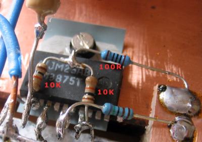
That depends on how much you think that the type of resistor affects the sound quality! I like to use carbon films and have used them for the input and feedback positions. I have used metal films for the grounded resistors. BTW - I measured the 5% carbon fi,m resistors to get exact matches for each channel. I may try something different like Welwyn RC55's at a later date.Does it matter that this necessitates a longer signal path?
I would say that if you keep the resistors soldered directly to the chip pins, then probably not. I have been told that there is nearly an inch (25 mm) of pins inside the chip body so I do not subscribe to the idea that a few millimeters more or less makes much (if any) difference.Does the T-network affect the working of the GC in any other way?
Not as far as I can tell. Certainly, in my two experiments it did not affect the temperature that the chips worked at.Last update: 2nd June 2009 - .Decibel Dungeon - Author Nick Whetstone