Site menu
Gainclone Index.
Gainclone FAQ.
Gainclone Gallery.
Introduction.
The circuit.
How does it sound.
Gainclone Index.
Gainclone FAQ.
Gainclone Gallery.
Introduction.
The circuit.
How does it sound.
Hung up on DIY hi-fi?
Then welcome to

Building a Gainclone (chip amp) with the LM3886.
![]()
![]()
Decibel Dungeon
<1>Introduction.
My circuit.
- Pin 5 is connected to the positive rail. You can do this with a simple wire link from pin 5 to pin 1.
- Pin 7 has to be connected to the signal ground star.
- Pin 8, the mute pin is connected to the negative supply pin (pin 4) via a resistor. The resistor value depends on the rail voltage and for 35-37 volt rails a resistor value of 18-22K is recommended. Also connected to the mute pin is a 100uF capacitor, the other side of which is connected to the signal ground star. Note the polarity of this resistor! (negative to pin 8 and positive to signal ground star)
- The signal input pins are different to the LM3875. Pin 9 is the inverting input and pin 10 the non-inverting input (ie the opposite way round to the LM3875 so be careful).
- The 0R22 output resistor should be rated at 3 watts. This may limit you to using a wire-wound resistor which some consider to sound poor in this part of the circuit. A better solution for this part is to use two 2 watt 0R47 carbon film resistors in parallel.
- The Zobel network on the output consists of a 100nF film capacitor in series with a 2R7 resistor (1/4 watt is fine here).
- The DC blocking cap should be a quality film (the best that you can get - I use polypropylene types) with a value between 2.2uF and 4.7uF.
- Keep all wiring as short as possible. Put the signal ground stars (shown as orange square) close to the chip, the power star between the capacitors on the voltage pins and the signal star right next to the chip as shown in the diagram above.
What does it sound like?
In short, much like the LM3875! I would guess that in two identical configurations, it would be almost impossible to tell them apart. In other words, the LM3886 sounds very good!
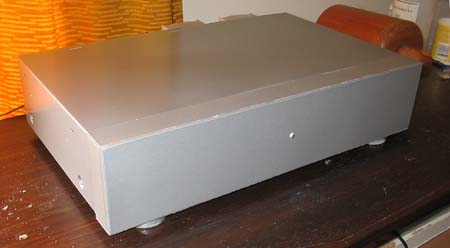
This is the finished LM3386 power amplifier which had a built-in PSU.
Last update: 28th July 2006 - Copyright © 2005 - Author Nick Whetstone