Hung up on DIY hi-fi?
Then welcome to

Building a Gainclone (chip amp) with a Resurrector.
![]()
![]()
Decibel Dungeon
Introduction.

Marek Klimczak.
The circuit.
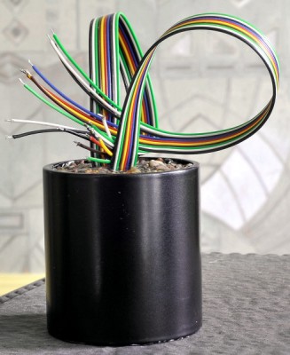
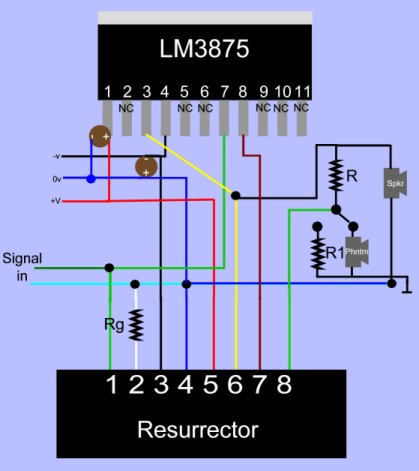
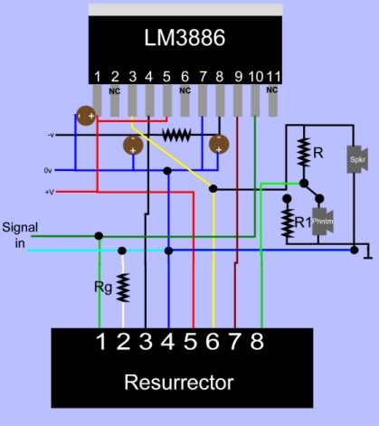
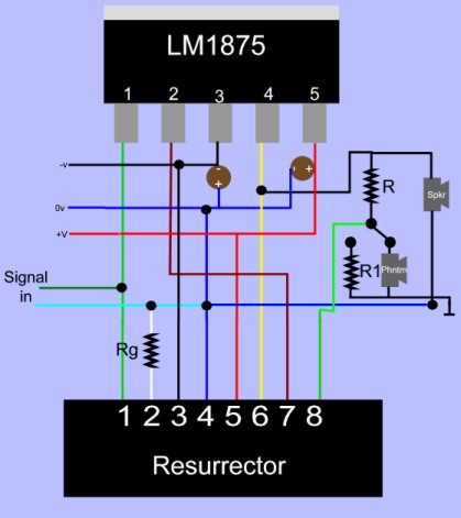
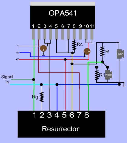
The Resurrector invention is the result of many years work, and understandably the inventor doesn't want to give away his secret. So the Resurrector comes encapsulated in a small pot (about 50mm diameter by 52mm long) that is filled with potting resin. The connections required to connect it to the chip amp are made via a pair of ribbon cables, each consisting of 8 separate wires. These are colour-coded as you can see from the picture, and providing that you don't mix up the duplicated colours, there is little to go wrong. Not being able to see all the components that you usually do can be a bit confusing, but if you stick to the wiring guide, you will be OK. The diagram below shows how a Resurrector is connected to an LM3875 chip.
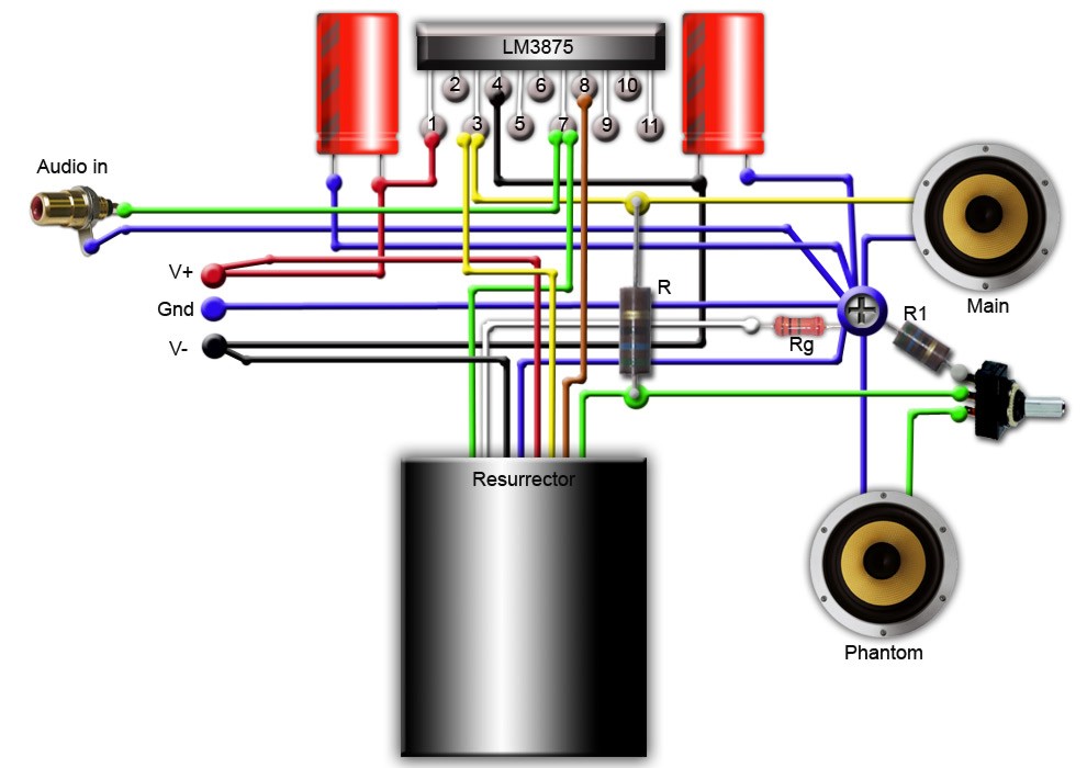
Diagram courtesy of Barry Twydell.
NOTE - R is twice the impedance of the phantom driver. R1 is four times the impedance of the phantom driver.
And here's a couple of pictures actually showing the connections.
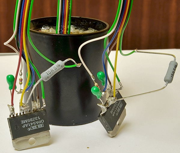
Connecting up the Resurrector.
As mentioned above the most likely mistake when using the Resurrector is to get the two green wires mixed up so be extra careful when soldering them. You can trim the wires shorter if you wish. Just make sure that you don't cut them too short. Also, note that these are stranded wires so make sure a stray strand isn't causing a short circuit somewhere! Working out where everything goes before you cut the wires is time well spent! In fact when you receive your Resurrector take plenty of time to work out where it will be located, and where all the wires go to. As ever in this game, a little careful planning can save you hours of problem-solving later!
| RG | Gain |
|---|---|
| 0r | 25-50 |
| 2K2 | 15-30 |
| 8K2 | 8-15 |
| 22k | 5-10 |
Do not go higher than 22k for the RG resistor or the amp will run the risk of clipping.
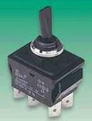
- a double pole double throw switch like the one shown below.
- A pair of 3 watt resistors about twice the value of the impedance of your phantom drivers. IMPORTANT - when powering your chip amp with the Resurrector included, you must have these resistors in circuit or your amp will die!
- Another pair of 3 watt resistors about twice the value of the other resistors.
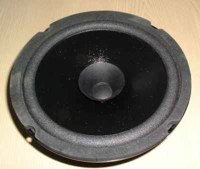
- A pair of drivers about the same impedance as the woofers in the speakers that your chip amp is driving. They don't need to be the same size or shape and you can alter the sound by using different phantom drivers. You don't have to spend a fortune on the phantom drivers. Believe me, I got great results with the pair of 8 inch drivers below that cost me less than 20 pounds for both of them.
- Not strictly necessary, but I used some terminal blocks to make holders for the 3 watt resistors, and the cables for the phantom drivers.
| Spkr imp. | R value | R1 value |
|---|---|---|
| 8 ohms | 16R | 32R |
| 6 ohms | 12R | 24R |
| 4 ohms | 8R | 16R |
IMPORTANT - keep the cables to the phantom drivers as short as is practical and preferably use screened (shielded) cables to hook them up with. If you don't and there is RFI about, it will get back into the amp and the sound will be too thin or bright.
Testing.
This is no different to testing a 'normal' chip amp except that you should test for DC offset on the outputs to the phantom drivers, as well as the main drivers. As ever, build and use a lightbulb tester for testing.Tuning.
You can obviously tune your chip amp in the usual way by changing resistors and capacitors, power supply etc. If you have tried that before, you know that you can make minor changes to the sound. The Resurrector offers a bit more latitude in tuning the chip amp. As mentioned above, by using different phantom drivers you can change the tonal balance of the Resurrectored chip amp. I found some SEAS bass drivers gave a more full-bodied sound than cheap full-range drivers, but the latter gave me a lightly more even overall tonal balance, and a bit more 'air'.As it's vitally important to the health of your chip amp, I'll repeat the warning. When powering your chip amp with the Resurrector included, you must have these resistors in circuit or your amp will die! If you use a variable resistor also make sure that you don't adjust the resistance below 4 ohms (alternatively use a 4 ohm stopper resistor as well).
Resurrector FAQ's.
Can the Resurrector be used with a chip amp built on a PCB?
Yes it can but you need to know the circuit that you are using quite well. What you will need to do is identify the feedback and input resistors and remove them from the PCB. This is because those items are already included in the Resurrector circuit. After removing the original resistors from the PCB you will need to identify where to add the wires from the Resurrector. By using a multimeter, you should be able to locate the pads on the PCB that connect to the various pins of the chip. It will be a little more complicated than building P2P but it can be done. If you have a PCB and want some help, let me know. Perhaps I can build a library of different PCBs so any potential Resurrector builder will have a reference.Can I make a true dual mono chip amp with a Resurrector?
Again, Marek has indicated that can be done, probably to special order.Does the Resurrector draw any power?
Not to my knowledge.What other changes do I need to make to a chip amp to include the Resurrector?
None apart from the Resurrector, resistors and phantom drivers. You don't need the switch and extra resistors for the comparison circuit although it is recommended. The PSU remains the same although I believe that you will find that smaller power supplies can be used with the Resurrector. I am getting excellent results with a pair of 80VA traffos but please note that my speakers are very efficient.How critical is the choice of phantom driver?
In a sense it is critical to get the driver that gives you the best sound. In another sense it isn't critical as almost any driver with a similar impedance to your main speakers will produce a big improvement. My advice is to go ahead and try the Resurrector with whatever you have or can get cheaply, and then look for better phantom drivers later.Can you hear the phantom drivers in use?
Yes if you put your ear really close to them. From the listening position you cannot detect that they are playing at all.Are there any harmful effects of using the Resurrector?
No. On my test-bed chip amp that uses the OPA541 chips, I get no noises at switch on or switch off. The chips don't run any warmer and there is no humming or buzzing at all.Why is the Resurrector circuit potted?
The Resurrector is the result of many years of research and the designer wishes to protect his secret as best as he can. Obtaining a patent is very difficult and he has decided not to try for one so potting up the circuit is the next best option.Can the Resurrector be used with inverting chip amp circuits?
The original Resurrector that I reviewed did complete an inverting circuit. But Marek has decided that the lower input impedance is unacceptable so all future Resurrectors will be for non-inverting circuits.Do I need a Resurrector with a chip amp that only powers a tweeter?
No, the Resurrector will have almost no effect with tweeters. So for an active speaker, use the Resurrector for the woofer section and a 'plain' chip amp for the tweeters.Do the cables connecting the phantom drivers make any difference?
Possibly. If the phantom drivers make a difference, the type of cables, or their length could also (to a much lesser degree) influence the sound. This is where we need people to experiment and report back with their findings.Do the phantom drivers need to be in an enclosure?
Only for neatness. And of course putting them in an enclosure will probably affect how they affect the amplifier. Again, time will provide the answer to this sort of question. Marek has even put his phantom drivers inside the enclosures of his main speakers.Questions.
I will add to the FAQ as and when I can. If you have any question about the Resurrector that isn't answered on this page, please ask. I will endeavor to get you an answer and then include that in the FAQ section. To ask a question, please click on the button below.
![]()
Resurrector connections.
In this section I'll show some typical circuit diagrams detailing where the Resurrector wires go to.
Last update: 23rd. February 2009 - Copyright © 2009 - Author Nick Whetstone